FORMWORK for Civil Engineering Construction Works Dr V


")


")


(10 cm) Putlogs (7. 5 x 7.")


 to")


")
- Slides: 63
FORMWORK for Civil Engineering Construction Works Dr V Srinivasa Reddy Professor of Civil Engineering GRIET Lecture 2 1
Formwork v. Falsework • Formwork includes Falsework • Formwork and Falsework are separate • Formwork is the Mould that holds fresh concrete • False work supports formwork and other structures (such as precast girders) There are two types of Formwork: 1. Vertical Forms 2. Horizontal Forms Vertical Forms are used to hold pressure Horizontal Forms are used to hold weight
Vertical Forms are used to form: ü Walls ü Columns ü Piers ü Abutments ü Beamsides ü Other Vertical Concrete Surfaces
Vertical Form: Wall Form
Vertical Form: Shear Wall
Vertical Form: Retaining Wall
Vertical Form: Sidewall/Abutment
Horizontal Forms • Horizontal Forms are used to form: üBridge Decks üFloors üOverhangs üOther Horizontal Concrete Elements
Horizontal Form: Metal Bridge Deck
Horizontal Form: Bridge Overhang
Horizontal Form: Bridge Overhang (Cantilevered Beams)
Pressure • Vertical Forms are designed to resist pressure. Form Pressure is affected by: üThe Concrete Mix üThe Rate of Placement üThe Temperature of the Concrete üThe Weight of the Concrete
Weight • Horizontal Forms are designed to hold the weight of the concrete. The design weight is determined by: üThe Depth of the Concrete üThe Unit Weight of Concrete üThe Amount of Reinforcing
Manufactured Forms What is the Pressure Capacity?
Job-Built Forms Is it designed according to specification? Is it constructed according to the design?
The Perfect Wall? ? Bad Joint Blemish
What do you think?
Is the concrete being placed properly?
Falsework Supporting Pier Cap Formwork
Falsework Supporting Precast Concrete Girders
NORMAL DEFECTS IN FORM WORK 1. The props or supports of form work were not in plumb and were not cross braced. 2. The ground supports (sills) to props or shores were poor and therefore the formwork settled. 3. Wedges were not tightened properly to the shores. 4. There was insufficient thickness of shuttering unable to bear lateral pressure imposed by wet concrete, specially in columns. 5. Shuttering plates were not cleaned and oiled or oiled with dirty oil. 6. There were many insufficient and loose connections in centering and shuttering. 7. Form work was removed before time. 8. Form work was not planned and designed properly. 9. In the case of beam forms, proper provision for retaining the side was not made. Hence, the concrete beam bulged on the sides. 10. The shuttering was poorly made with cracked and warped timber planks having lot of holes and knots. 11. Through bolts for the R. C. C. walls form work for an underground tank were used. Later the holes made by the bolts could not be plugged. 12. 'Ballis' were resting on bricks or brick pillars.
Formwork for Foundations • Wall foundations • It consists of • Plywood Sheeting • Struts
Formwork for Foundations • Column Foundations • It consists of • Side Supports • Side Planks • Cleats Side Support Side Planks
Formwork for Wall Vertical Posts • It consists of • • • Timber sheeting Vertical posts Horizontal members Rackers Stakes Wedges • After completing one side of formwork reinforcement is provided at the place then the second side formwork is provided. Struts
Formwork for Column • It consists of the following • Side & End Planks • Yoke • Nut & Bolts • Two end & two side planks are joined by the yokes and bolts.
Formwork for Slabs & beams • It consists of • • Sole plates Wedges Props Head tree Planks Batten Ledgers • Beam formwork rests on head tree • Slab form work rests on battens and joists • If prop height are more than 8’ provide horizontal braces.
Formwork for Stairs • It consists of • Vertical & inclined posts • Inclined members • Wooden Planks or sheeting • Stringer • Riser Planks
Removal of formwork Time of formwork removal depends on the following factors 1. Type of Cement Rapid hardening cements require lesser time as compared to OPC (Ordinary Portland Cement) 2. Ratio of concrete mix Rich ratio concrete gain strength earlier as compared to weak ratio concrete. 3. Weather condition Hydration process accelerates in hot weather conditions as compared to cold and humid weather conditions.
Time of Removal of formwork OPC Rapid Hardening Cement Structural Member (Ordinary Portland Cement) Beam sides, walls & Columns 2 -3 Days 2 Days Slab (Vertical Supports remains intact) 4 Days 3 Days 10 Days 5 Days 8 Days 5 Days 14 Days 5 -8 Days 21 Days 8 -10 Days Slab (Complete Formwork removal) Beams (Removal of Sheeting, Props remains intact) Beams & Arches (Complete formwork removal) (up to 6 m span) Beams & Arches (Complete formwork removal) (more than 6 m span)
Maintenance of formwork • Due to continuous use wooden planks & steel plates surfaces become uneven and require maintenance. • For wooden formwork use cardboard or plastic fiber board. Bolt hole places must also be repaired. • For steel formwork plates must be leveled by mallet and loose corners must be welded.
Cost of formwork • For normal works cost of formwork is about 30%-40% of the concrete cost. • For special works cost of formwork is about 50%-60% of the concrete cost. • Formwork cost is controlled by the following factors • Formwork Material cost • Formwork erecting cost • Formwork removal cost • Formwork jointing cost (Nails and Cables) • Labor charges.
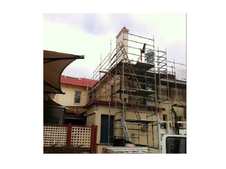
Types of Scaffolding Following are the types of scaffolds • Brick layer’s Scaffolding or Single Scaffolding • Mason’s Scaffolding or Double Scaffolding • Ladder Scaffolds • Needle Scaffolding or Cantilever Scaffolding • Suspended Scaffolds • Steel or Tubular Scaffolds
Definition • Scaffold • It is the temporary support system provided for the construction & maintenance purposes. • It consists of supports and a working platform for workers and Materials. • Scaffolding • Method of construction of scaffolds is called scaffolding.
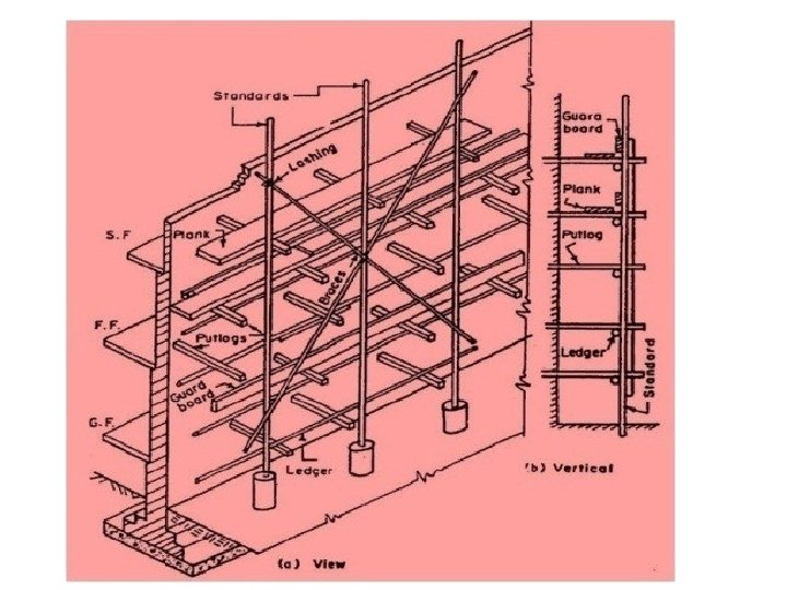
Single Scaffolds It consists of Standards (v posts)(10 cm) Putlogs (7. 5 x 7. 5) Ledgers ( Wooden boards Braces Used for ordinary buildings 1. 2 m
The distance in between two standards is generally kept within 2. 4 to 3 m. These standards are connected to each by a longitudinal horizontal member (named as Ledgers). Ledgers are tied with standards at every rise of 120 cm to 150 cm (i. e. 4 ft to 5 ft). Rope lashing is used to tie the standard with ledgers. The putlogs (or transverse horizontal members) are placed at a horizontal spacing of 120 cm such that one end is supported on the ledgers and the other end is held in the holes made in the wall. Rope lashing is used to fasten the putlogs with ledgers. If the height of the scaffolding is very high, to maintain its stability, sometimes diagonal members (named as Braces) are provided. Braces are cross diagonally fitted with the standards using rope lashing.
Double Scaffolds It consists of Two rows of standards. 15 cm, 1. 5 m Shores are provided. Used for superior works
This type of scaffolding is commonly used in case of stone masonry. It is stronger than brick layer’s scaffolding. The primary differences between brick layer’s scaffolding and mason’s scaffolding are as follow: • In case of brick layer’s scaffolding single row of standard is fixed into the ground. But in case of mason’s scaffolding two rows of standards are fixed into the ground. • First row of standards is fixed close to the wall and second row of standard is fixed at a distance of 1. 5 m from the first row. This is why it is named as double scaffolding. • In case of brick layer’s scaffolding one end of putlog is fixed with wall. But in double scaffolding, putlogs are not fixed with the wall. Put logs are supported at both ends on ledgers. Therefore mason’s scaffolding is completely independent of the wall surface. And there is no need to make any hole on the wall surface. Sometime raking shores are provided to prevent the slipping of scaffolding away
Ladder Scaffolds • It consists of • Brackets for Plate form.
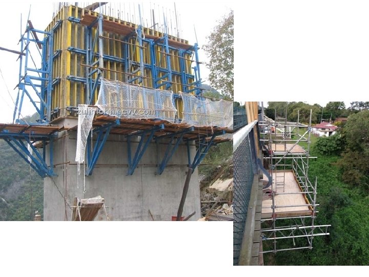
Cantilever Scaffolds It consists of Cantilever Struts Standards Putlogs Plate forms It is used above ground level
Needle scaffolding or cantilever scaffolding is required in the following cases • When it is not possible to fix standard into the ground • When construction is done on the side of a busy street • When construction work is carried out at very high level in case of tall building In this type of scaffolding instead of fixing the standard into the ground, it is placed at some height above the ground level. The platform on which stands are placed is called needle. A needle is a cantilever structure, made of timber, projected out from the holes in wall.
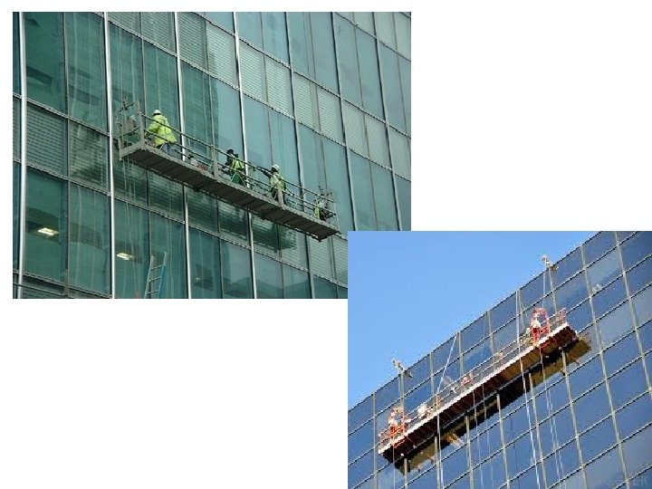
Suspended Scaffolds It consists of Ropes Working platforms Ropes can be raised Manually or mechanically Used for light construction and finishing works of multistory buildings.
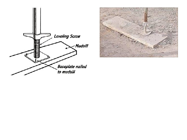
Steel or Tubular Scaffolds • It consists of • Steel tubes (1 -1/2” – 2 -1/2” diameter) • Coupler or Clamps (to hold pipes in different positions) • Prop nuts (to hold single pipes) • Bolts, Nuts & washers • Wedge & Clip
Scaffold pipes
Coupler or Clamps
Scaffold fittings • Double Coupler • It joins ledgers and standards. • Swivel Coupler • Composed of two single couplers and used to join two scaffolds at any angle. • Putlog Coupler • Used to join putlogs with transom. • Base Plate • Used at the base of the standards. • Split joint Pin • It’s a connection fitting used to join scaffold tubes. • Reveal Pin • It fit in to the end of a tube to form an adjustable strut. • Putlog end • A flat plate used at the end of a scaffold to convert it in to a putlog.
Prop nuts, clamp and fasteners
Wedge & Clip
The method of construction of steel scaffolding is similar to that of brick layer’s and mason’s scaffolding. The primary differences are • Instead of using timber, steel tube of diameter of 40 m to 60 mm are used • Instead of using rope lashing, special types of steel couples are used for fastening • Instead of fixing the standards into the ground, it is placed on base plate The gap between two standards in a row is generally kept within 2. 5 m to 3 m. These standards are fixed on a square or round steel plate (known as Base Plate) by means of welding. Ledgers are spaced at every rise of 1. 8 m. Length of the putlogs are normally 1. 2 m to 1. 8 m.
Advantages of the Steel Scaffolds are as follow: • It can be erected or dismantled more rapidly in comparison to timber scaffolding. This helps in saving construction time. • It is more durable than timber. Therefore it is economical in long run. • It has more fire resisting capacity • It is more suitable and safe to work at any height.
Shoring • Definition • It is the method of providing temporary support (shores) to an unsafe structure. • Types of Shoring • Horizontal shoring or flying shoring • Vertical shoring or dead shoring • Inclined Shoring or flying shoring
Horizontal shoring It consists of Horizontal beam or strut Wall plates Cleats Straining beams Used to support two adjacent buildings.
Single Flying Shoring
Double Flying Shoring
Vertical shoring It consists of Dead shores Sole plates Needles Props Used for rebuilding of walls.
tical Ver d or Dea ring Sho
Inclined Shoring It consists of Rackers Needles Cleats Braces Sole plate Used to strengthen a wall.
Inclined or Raking Shoring
Inclined or Raking Shoring (unsymmetrical)