Formulation of Characteristic Equations for Instruments P M


 eddies may be Estimated as:")


 Rated Output(m V/V) Compensated Temp. Range")


 Ttf(t) Rs Rcond Rtf Change in energy of thermometer:")


- Slides: 27
Formulation of Characteristic Equations for Instruments P M V Subbarao Professor Mechanical Engineering Department Clues for Design of an Instrument to carry out Transient Measurements….
Characteristic Equation of A General Instrument The characteristic equation of nth order system:
Laplace Transformations for Instruments
Generalized Instrument System : A combination of Blocks The response analysis can be carried out to each independent block.
A True Instrument • A true instrument should consist of only Zero-Order Blocks • To investigate the response of a block, multiply its frequency domain form of characteristic equation with that of the chosen input equation. • This is an interesting case because Equation shows that the zero-order block has no frequency dependent term, so the output for all given inputs can only be of the same time form as the input. • What can be changed is the amplitude given as the coefficient a 0. • A shift in time (phase shift) of the output waveform with the input also does not occur. • This is the response often desired in instruments because it means that the block does not alter the dynamics of input signal. • The final destination of research in instrumentation is to find a true zero order instrument for every measurement.
Description of Turbulent Flow : Lessons from Nature A Hurricane : THE VORTEX
Experimental Research in Turbulence The size of energy-containing (largest) eddies may be Estimated as: The Structure of Vortex The vortical structures visualized by iso-surfaces of vorticity and Laplacian of pressure. where, ω = ∇×u is the vorticity.
Distribution of Vortices in a Turbulent Field |ω| Iso-surface representations of vortical structures
Non-dimensional Energy of eddy True Structure of Turbulent Flow Only zero order probes can measure true Turbulence !!! 1/size of vortex
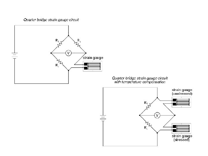
Zero Order Instrument: Wire Strain Gauge This is the response often desired in instruments because it means that the block does not alter the time response. All instruments behave as zero order instruments when they give a static output in response to a static input.
Wire Strain Gauge
Wire Strain Gauge Pressure Transducers In comparison with other types of pressure transducers, the strain gage type pressure transducer is of higher accuraciy, higher stability and of higher responsibility. The strain gage type pressure transducers are widely used as the high accuracy force detection means in the hydraulic testing machines.
Micro Sensor Technology Tokyo Capacity Range Nonlinearity(% RO) Rated Output(m V/V) Compensated Temp. Range (℃) Type Features and Applications HVS High Accuracy type 0. 5, . . 50 MPa 0. 2, 0. 3 1. 0, 1. 5± 1 % -10 to 60 HVU General Purpose type 1, . . 50 MPa 0. 3, 0. 5 1. 5, 2. 0± 1 % -10 to 60 HVJS Small & High Temperature type 1, . . 50 MPa 0. 5 1. 0, 1. 5± 20 % -10 to 150 HVJSJS Small & High Temperature type, Vibratio n-proof 1, . . 10 MPa 0. 5 1. 0, 1. 5± 20 % -10 to 150
First Order Instruments • A first order linear instrument has an output which is given by a non-homogeneous first order linear differential equation • In these instruments there is a time delay in their response to changes of input. • The time constant t is a measure of the time delay. • Thermometers for measuring temperature are first-order instruments.
• The time constant of a measurement of temperature is determined by thermal capacity of thermometer and thermal contact between thermometer and the body whose temperature is being measured. • A cup anemometer for measuring wind speed is also a first order instrument. • The time constant depends on the anemometer's moment of inertia.
Development of Characteristic Equation for Liquid–in –Glass Thermometer
Liquid in Glass Thermometer material alcohol, ethyl gasoline jet fuel, kerosene mercury water, liquid (1 ℃) water, liquid (4 ℃) water, liquid (10 ℃) water, liquid (20 ℃) water, liquid (30 ℃) water, liquid (40 ℃) water, liquid (50 ℃) water, liquid (60 ℃) water, liquid (70 ℃) water, liquid (80 ℃) water, liquid (90 ℃) volume g (10− 6 K− 1) 1120 950 990 181 − 50 0 88 207 303 385 457 522 582 640 695
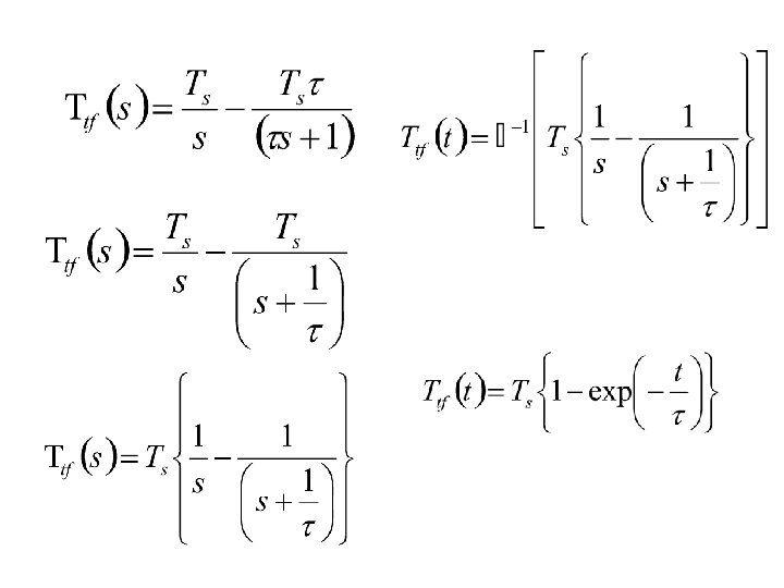
Development of Characteristic Equation for a Thermometer Conservation of Energy during a time dt Heat in – heat out = Change in energy of thermometer Assume no losses from the stem. Heat in = Change in energy of thermometer
Ts(t) Ttf(t) Rs Rcond Rtf Change in energy of thermometer:
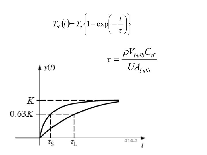
Step Response of Thermometers Define Time constant
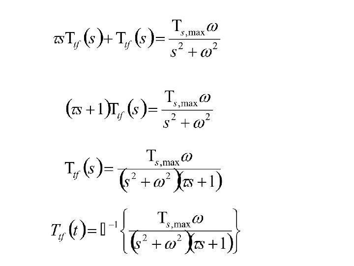
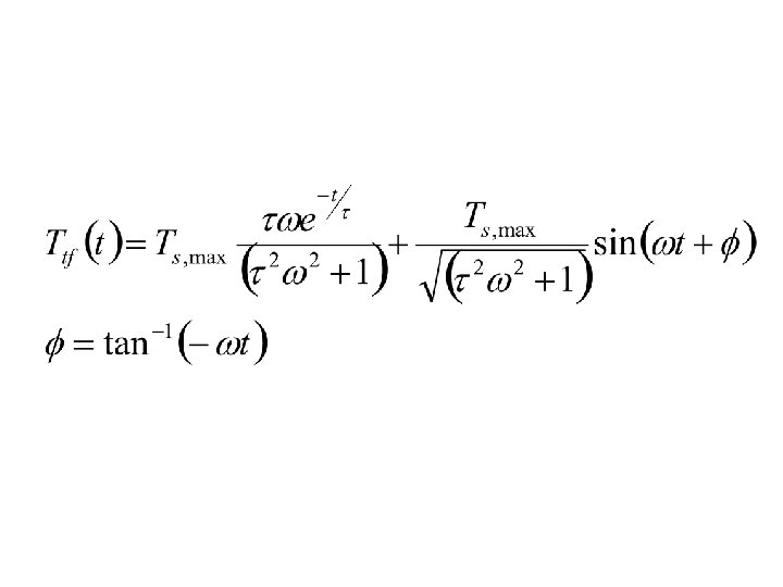
Response of Thermometers: Periodic Loading • If the input is a sine-wave, the output response is quite different; • but again, it will be found that there is a general solution for all situations of this kind.
f Ts, max- Ttf, max