Formula SAE Turbocharger Problem Statement Successfully implement a

Formula SAE Turbocharger: Problem Statement: Successfully implement a turbocharger system on the current WR 450 single cylinder engine.

Background:

Functional Decomposition:

Constraints: 1. 2. 3. 4. 5. 6. Engine compartment restrictions from chassis Minimize system weight Cost (With or without sponsorship) Maintain controlled temperature Spares for all parts must be available FSAE rules and regulations
 Yamaha Phazer Turbo Origin Honeywell/Garrett IHI")
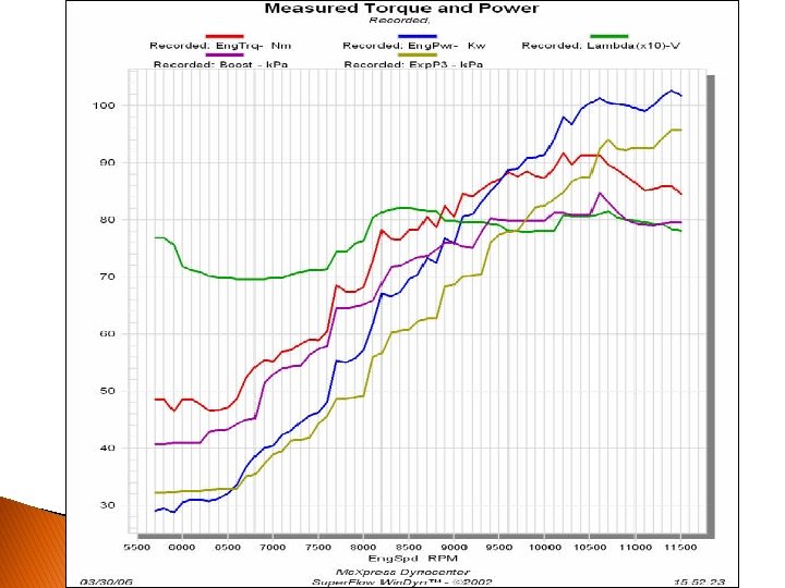
Object Honeywell Turbo University of Wisconsin FSAE (2010) Yamaha Phazer Turbo Origin Honeywell/Garrett IHI wastegate controlled (RHF 3) Mitsubishi brand turbo Cost $643 - $5, 499 (full kit for snowmobile) GT 12 Family Smallest produced by Garrett 50 -130 hp range Recommended 400 cc to 1200 cc engine size Journal Bearing system Oil & Water Cooling Japanese Manufacturer Running KTM 525 XC Compression Ratio - 10. 4: 1 Kit for Yamaha Phazer 4 stroke 500 cc engine Produces 136 hp (unrestricted) E-85 ethanol at 12 psi max power design at 7600 RPM max torque design at 6000 RPM min RPM for 80% max torque 5000 RPM 3. 5 Bar fuel pressure 1400 cc intake plenum volume Max spark advance: 29 deg BTDC at 9000 RPM WOT small, fast reacting turbo Turbine Wheel: 35. 5 mm Turbo in series with engine dry sump Trim: 72 A/R: 0. 43 Internally Wastegated No intercooler Wiseco forged piston Information Inducer: 29 mm Exducer: 41 mm Trim: 50 A/R: 0. 33 Most efficient between 0. 7 -1 Bar boost
 CN 1 Engine")
Difficulty Unit of Measure Ideal Value Source Function Specification (metric) CN 1 Engine Peak Power Output S 2 CN 1, 2 Intake Mass Air Flow g/s >=50 Maximize for restrictor S 3 CN 1, 2 Intake Plenum Volume cc >=1000 S 4 CN 3 Sensors Sensor Voltage V 5 S 5 CN 1, 5, 15 Intercooler Air Temperature Reduction Deg F >=20 May not be needed S 6 CN 1, 2, 5 Intake Manifold Air Temperature Deg F S 7 CN 1, 7, 9 Turbo Turbine Shaft RPM rpm Depending on turbo chosen S 8 CN 1, 7, 9 Turbo Intake Manifold Pressure psi <=100 ~100, 00 0 >=20 S 9 CN 7, 9, 13 Turbo Peak Compression by RPM (specified) rpm <=6000 S 10 CN 2, 3 Sensors Air Fuel Ratio Range S 11 CN 1, 3 Sensors Manifold Air Pressure Range psi 0 -30 S 12 CN 3, 4, 13, 17 Turbo Pressure to Actuate Wastegate psi >=20 S 13 CN 1, 17 Exhaust Flow Rate g/s >=100 S 14 CN 8 Exhaust Noise Level d. Ba <110 S 15 CN 3, 5, 7, 16 Turbo Max Temperature of Turbo Deg F <800 S 16 CN 7, 11, 18 System Overall Maximum Weight Increase lbs <=15 S 17 CN 1, 3, 4, 6 Engine Compression Ratio S 18 CN 1, 13 Engine Max Power Design RPM rpm ~9000 S 19 CN 1, 13 Engine Max Torque Design RPM rpm ~7000 S 20 CN 1, 3, 13 Engine Max Spark Advance deg 40 -45 S 21 CN 4, 16, 18 Funding Cost to Formula Team $$$ <100 S 1 Hp and ft- >= 60 hp lbs 45 ft-lbs Comments/Status General increase overall can also compensate 12. 6<x< 17. 6 ~10: 1 Based on FSAE regulation Max achievable without engine knock Funding/Sponsorship will be required
 Plenum Volume (Intake) Sensor Voltage Air Temperature Reduction (intercooler) Manifold")
Mass Air Flow (Intake) Plenum Volume (Intake) Sensor Voltage Air Temperature Reduction (intercooler) Manifold Air Temperature Turbine Shaft RPM Intake Manifold Pressure Peak Compression by RPM (specified) Air Fuel Ratio Range Manifold Air Pressure Range Pressure to Actuate Wastegate Flow Rate (Exhaust) Noise Level Max Temperature of Turbo Overall Maximum Weight Increase Compression Ratio Max Power Design RPM Max Torque Design RPM Max Spark Advance Cost to Formula Team Overall HP & Torque Gains Optimized ECU Map Consistent Performance Necessary Engine Internals Adequate System Cooling Sufficient Dyno Testing Optimized Turbo Size for Application Meet FSAE Noise Regulations Quick Throttle Response Easy to Access in Car Compact Design in Car Fit Within Constraints of Chasssis Easy to Drive Design Drivetrain Components for Power Increase Design for Intercooler Location Readily Available Replacement Parts Simple interface with Current Engine Maximize Use of Composite Materials Peak Power Output Customer Needs Specifications X X X X X X X X X X X X X X X X X X X X X X X X

Staffing: Qty Description Responsible for system integration with chassis, engine, drivetrain, and electrical components. Also responsible for management duties, and engine calibration Lead (ME) 1 Thermal (ME) 1 Responsible for heat management of the system. Will require work with FEA, Pro Engineer, Heat Transfer, and System Dynamics 2 Responsible for fluid flow analysis through each individual subcomponent of the system. Will require work with CFD, Pro Engineer, Fluid Mechanics, System Dynamics, IC Engines, and FEA 1 Responsible for structural integrity of the system. Will require analysis of vibration and stresses through use of FEA, Pro Engineer, Statics, and System Dynamics. Fluids (ME) Structures (ME) *Formula SAE experience preferred for all positions
: � Main concern with scope is time constraints")
Customer Meeting Feedback (FSAE Powertain Engineer): � Main concern with scope is time constraints ◦ Project may be used as development for future cars rather than implementing on F 21 ◦ Lessons learned can be advantageous in design competition ◦ Cost may be an issue without appropriate sponsorships � Specifications are reasonable, some flexible ◦ Overall system gains must justify weight and cost increase ◦ Expected to set ambitious goals for top ranking car � Project staffing is realistic ◦ Communication between team members will be crucial to the quality of the project

Questions?
- Slides: 11