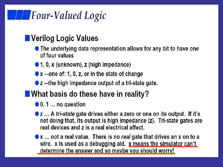
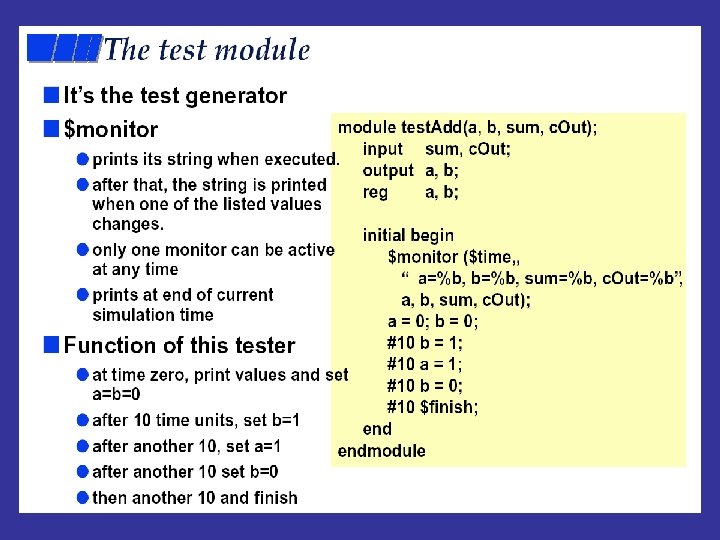
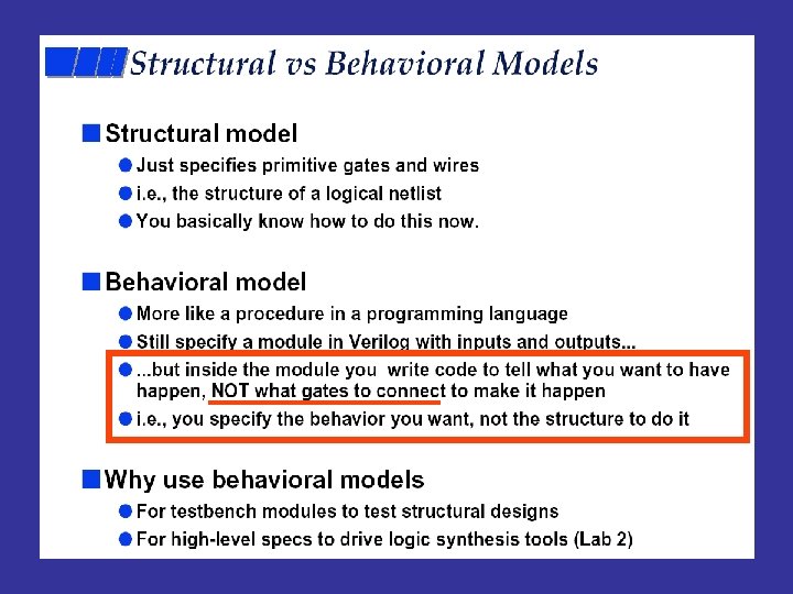
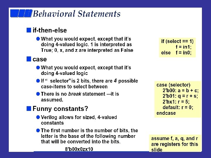
Formalni postupci u oblikovanju raunalnih sustava2008 Auditorne1 03
 Auditorne_1: 03. 2008. , 14: 00 – 16:")
Formalni postupci u oblikovanju računalnih sustava(2008) Auditorne_1: 03. 2008. , 14: 00 – 16: 00, D 1 Pred. (Logika) 07. 03. 2006. , 09: 15 – 11: 00 B 4 Auditorne_2: 10. 03. 2008. , 08: 00 -10: 00 D 1 Test sustava: 10. 03. 2008. , 14: 00 – 16: 30 A 102 Prvi lab otvoren: 10. 03. 2008. , 16: 30 – 18: 00 A 102 Pred. (CTL) 14. 03. 2008. , 09: 15 – 11: 00 B 4 Auditorne_3: 17. 03. 2008. 08: 00 – 10: 00 D 1 Prvi lab kolokvij: 17. 03. 2008. , 14: 00 – 16: 30 A 102, 101 Za raspored po grupama vidi Web stranicu labosa
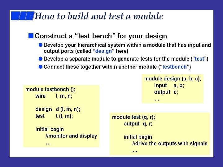
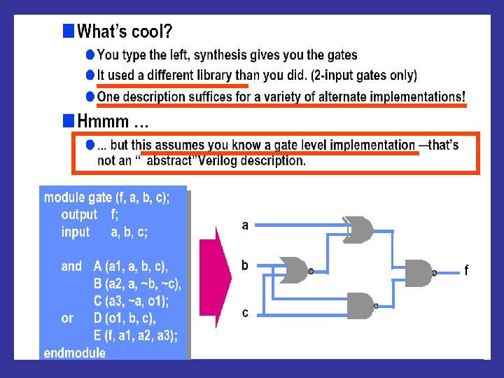
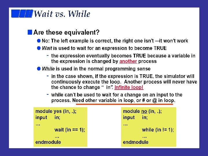
 YES Verifier")
Formal verification I = Implementation (model of the system to be verified) YES Verifier NO (error trace) S = Specification (behavior) Expressed in temporal logic 1. How to model I ? 2. What is 3. How to model S ? I S
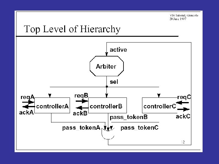
 Verifikacija sklopovlja Primjer: Arbitar sabirnice Opis implementacije (I): Verilog (HDL) Opis specifikacije")
A 1) Verifikacija sklopovlja Primjer: Arbitar sabirnice Opis implementacije (I): Verilog (HDL) Opis specifikacije (S): CTL Sustav za verifikaciju: VIS A 2) Verifikacija dijelova programskih produkata Primjeri: Međ. isključ. proc. Opis implementacije (I): SMV Opis specifikacije (S): CTL Sustav za verifikaciju: SMV
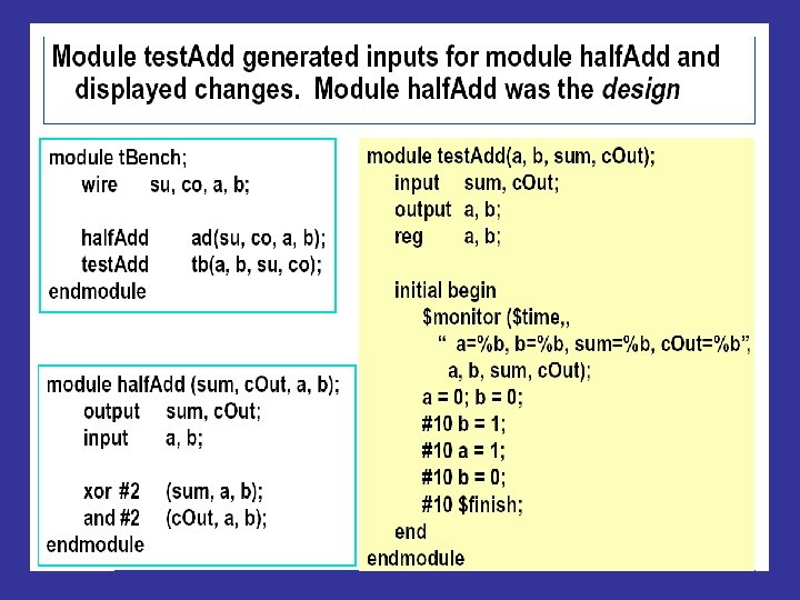
 Laboratorijske vježbe iz verifikacije sklopovlja: Arbitar sabirnice (engl. Bus Arbiter) Opis implementacije")
A 1) Laboratorijske vježbe iz verifikacije sklopovlja: Arbitar sabirnice (engl. Bus Arbiter) Opis implementacije ( I ): Verilog Opis specifikacije ( S ): CTL vremenska logika Sustav za verifikaciju: VIS

VIS: http: //www-cad. eecs. berkeley. edu/~vis I = foo. v VHDL Verilog SMV Blif-mv S = bar. ctl CTL Simulation F = go. fair Move around View hierarchy Verification PASS FAIL (error trace) Fairness Synthesis SIS
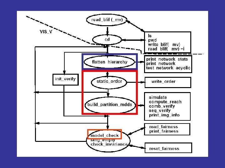


Na stranicama lab. vježbi VIS dokumentacija Za implementaciju I: 1. VIS User Manual 2. Verilog – kratki opis 3. Verilog – pregled naredbi Za specifikaciju S: 1. VIS CTL Manual
, sintaktički posudio mnogo od C-a. • Opis")
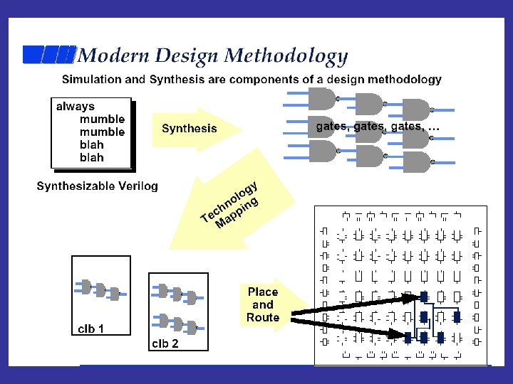
VERILOG • Jezik za opis sklopovlja (HDL), sintaktički posudio mnogo od C-a. • Opis na više razina apstrakcije. • IEEE standard #1364 - 1995. • Verilog datoteke se mogu verificirati, simulirati i sintetizirati. Ref. : 1. Donald E. Thomas and Philip R. Moorby The Verilog Hardware Description Language, 4 th Ed. Kluwer, 1998. (Carnagie Melon University) 2. http: //www. ovi. org (VERILOG i VHDL)


g 1 f 1 nsel g 2 f 2

")
addition Second: temp store before assign (Logical OR = II)
")
(anything can be accessed, bad style)
 same as a. e since no")
This e is different (it is top e) same as a. e since no local e

AB e logic only Inputs: A B C D e Ex. 1 1 0 1 = char. “d” e = 1 (ON) CD

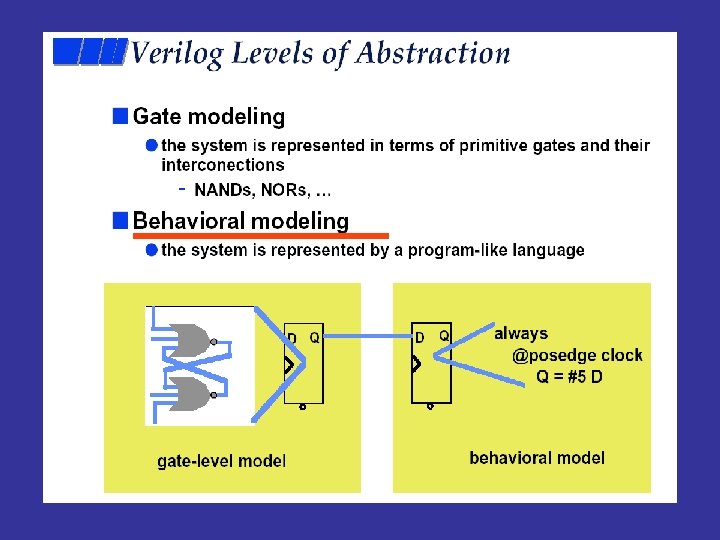
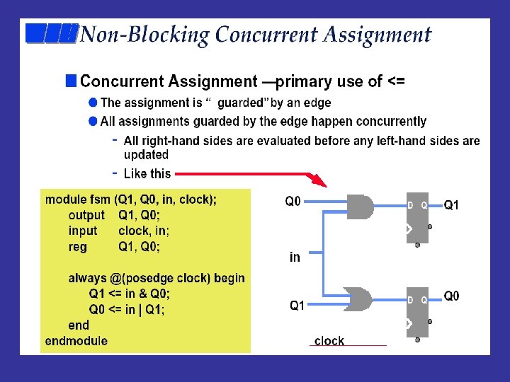
neg. edge reset pos. edge 0 1 00/0 0 1 01/1 clock 1 11/0 0 Output State Input module fsm(out, in, clock, reset); output out; input in, clock, reset; reg out; reg [1: 0] current. State, next. State; // combination portion * * * // sequential portion * * * endmodule
 begin Bit select out = ~current.")
// combination portion always @(in or current. State) begin Bit select out = ~current. State[1] & current. State[0]; = 01 // out = 1 only for state 01 next. State = 0; if (current. State == 0) if(in) next. State = 1; //else stay in 0 if (current. State == 1) if (in) next. State = 3; //else go to 0 if (current. State == 3)begin if (in) next. State = 3; else next. State = 1; end // the sequential portion always @(posedge clock or negedge reset) begin if (~reset) current. State <= 0; // as long as res=0 else current. State <= next. State; // as D type bistable end Non blocking
 Enumerated types ( similar to C ) typedef enum")
Verilog extensions (in VIS environment) Enumerated types ( similar to C ) typedef enum {IDLE, READY, BUSY} controller_state; /* contr. _state is an enum type */ controller_state reg state; /* state is a register variable of the type “controller_state” */

Non-determinism There exist state-input pair for which the next state and output are not unique. $ND construct • creates a nondeterministic signal source • should only be used in an assign statement wire r; /* def of a wire variable */ assign r=$ND(GO, NOGO); /* nondeterminism */. . always@(posedge clk) begin. . state = r; /* the state is nondeterm. GO or NOGO */. . end

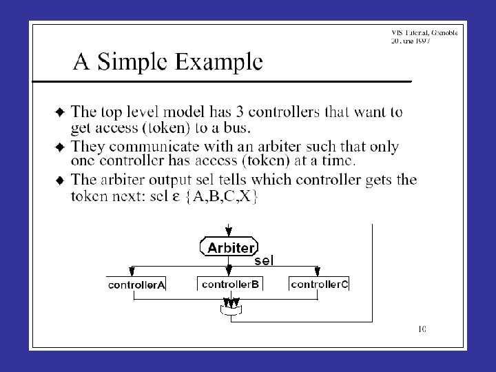
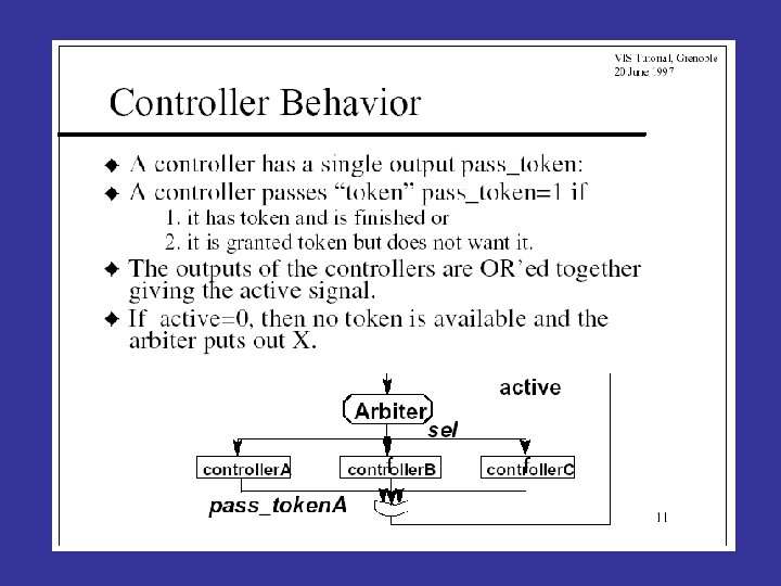
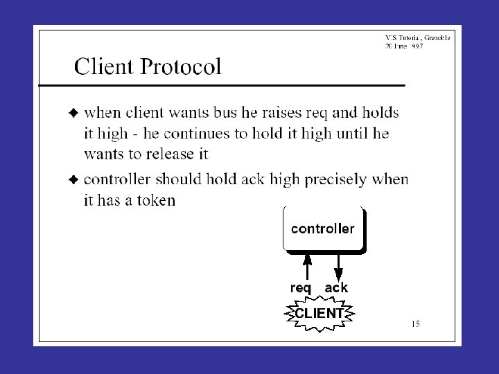
Example: Arbiter client. A client. B client. C
; … // typedef … // input, output, wire, reg. . . controller.")
module main(clk); … // typedef … // input, output, wire, reg. . . controller. A(clk, req. A, ack. A, sel, pass_token. A, A); controller. B(clk, req. B, ack. B, sel, pass_token. B, B); controller. C(clk, req. C, ack. C, sel, pass_token. C, C); arbiter(clk, sel, active); client. A(clk, req. A, ack. A); client. B(clk, req. B, ack. B); client. C(clk, req. C, ack. C); endmodule controller(clk, req, ack, sel, pass_token, id); input clk, req, sel, id; output ack, pass_token; …. endmodule arbiter(clk, sel, active); input clk, active; output sel; . . . endmodule client(clk, req, ack); input clk, ack; output req; . . . endmodule
 Laboratorijske vježbe iz verifikacije programskih dijelova: Algoritmi međusobnog isključivanja procesa (mutex) Opis")
A 2) Laboratorijske vježbe iz verifikacije programskih dijelova: Algoritmi međusobnog isključivanja procesa (mutex) Opis implementacije ( I ): SMV Opis specifikacije ( S ): CTL vremenska logika Sustav za verifikaciju: SMV

SMV - Symbolic model verifier Ken Mc. Millan, CMU, Ph. D. thesis, 1992. Formalni model (/) - SMV sintaksa Formalna specifikacija (S) - CTL formule foo. smv I Da / Ne (+ error trace) SMV sustav za verifikaciju S
: stroj s konačnim brojem stanja (FSM) u SMV kodu request")
Implementacija ( I ): stroj s konačnim brojem stanja (FSM) u SMV kodu request = {0, 1} (npr. 1=True, 0=False) req = 1 st. =ready st. =busy req = 0 st. =ready st. =busy status = {ready, busy}

MODULE main // foo. smv file VAR request: status: boolean // type boolean {ready, busy} // type sclr {ready, busy} init (status) : = ready; // init status value next (status) : = case // next status value ASSIGN request : busy; // if st=rdy req=1 in crnt state, then next st=bsy 1 : {ready, busy}; // else not det. esac; SPEC AG(request -> AF status = busy) // CTL spec.

MODULE main // ring of 3 inverters, each with diff. speed VAR gate 1 : process inverter(gate 3. output); gate 2 : process inverter(gate 1. output); gate 3 : process inverter(gate 2. output); // SMV chooses and runs any process module nondeterminist. // useful to describe parallel processes, e. g comm. protocols SPEC (AG AF gate 1. out) & (AG AF !gate 1. out) MODULE inverter(input) VAR output : boolean; ASSIGN init(output) : = 0; next(ouput) : = !input; // output inverts input with type chk
- Slides: 59