Ford EEC IV Operation and Testing Overview ECT


 Hall Effect Switch Engine speed and crank position In distributor")
 On DIS sensor is on front of engine One vane")
 Used with Distributorless Ignition PIP doesn't know which stroke Driven at")


 Piezoelectric type Vibration sends signal to PCM retards timing 1/2 o")
 Was called Air Charge Temp (ACT) before OBDII Thermistor")
 Feedback (PFE) EVP Linear Potentiometer l only monitors position EVP Black")
 Used with VAT and BP to calculate Speed Density")


 Speedometer output l Mechanical or electric speedometer. 8 cycles per")


")


")
 Group or bank-to-bank l Two Groups Sequential (SEFI) Injectors")


 Thick film refers to the type of semiconductor Controls spark")
")
 TFI Module Closed Bowl Octane rod can change base timing")


 Thermactor Air Diverter (TAD) PCM Controlled")


 After last code, deactivate and reactivate self test l")

- Slides: 76
Ford EEC IV Operation and Testing
Overview ECT MAP/BARO TPS CKP/CMP O 2 S EGR Position ACT KS BOO AC Power Steering PCM A/F Mixture Ignition Timing Idle Speed Thermactor Airflow Canister Purge EGR Flow TCC AC Fan WOT Cut Off Inlet Air Temp Fuel Pump Relay Turbo Boost
Operating Modes Base Engine Strategy MPG Lean Cruise Modulator Strategy Limited Operational Strategy Adaptive Strategy
Base Engine Strategy Used to control warm engine running Open Loop starts at 130 o l Warm up mode sub modes l Cranking l Closed-throttle l Part throttle (closed loop) l Wide-open throttle (WOT) l l PCM controls actuators for good driveability
MPG Lean Cruise Some engines beginning 1988 Certain criteria are met Goes out of closed-loop fuel control Very lean for economy at cruise
Modulator Strategy Conditions that require significant change from Base Engine Strategy Cold engine l Overheated engine l High altitude l
Limited Operational Strategy Component Failure Protect other components l Converter Substitute values from another sensor MAP l ECT l EGR l TPS IAT Disable EGR
Adaptive Strategy Started in 1985 PCM has base map Monitors operation and modifies base map Compensates for wear etc. l Dirty Injectors Are in response to O 2 S Stored in KAM
Adaptive Strategy
Adaptive Strategy
Adaptive Strategy
Adaptive Strategy
Inputs ECT MAP/BARO TPS CKP/CMP O 2 S EGR Position ACT KS BOO AC Power Steering PCM A/F Mixture Ignition Timing Idle Speed Thermactor Airflow Canister Purge EGR Flow TCC AC Fan WOT Cut Off Inlet Air Temp Fuel Pump Relay Turbo Boost
Engine Coolant Temp Thermistor Voltage to PCM is 4. 5 cold to. 3 hot Resistance 470 K cold to 1 k hot Influences PCM’s calibrations for l l l A/F Raito Idle Speed Thermactor Air Canister Purge Choke Voltage, Temp compensated accel pump Upshift light
Pressure Sensors MAP, BARO Pressure-sensitive capacitor Convert to frequency out 100 Hz no load Idle l 159 Hz atmospheric (WOT) l Voltage will go from 0 to 5 at the frequency above
Pressure Sensors MAP used for BARO l PCM uses Key On before cranking and WOT for BARO calculations. BARO used with Vane Airflow Sensors Looks like MAP with collar
Throttle Position Sensor Some adjustable, some not Potentiometer 3 wires, 5 v reference, ground, signal Two common problems Bad spot, signal dropout l Bad ground l Full reference on signal l Biased high l
Profile Ignition Pickup (PIP) Hall Effect Switch Engine speed and crank position In distributor One vane narrower for location
Profile Ignition Pickup (PIP) On DIS sensor is on front of engine One vane for each pair of companion cylinders Most PIP signals go from. 4 v or less to battery voltage at 10 o BTDC
Cylinder Identification (CID) Used with Distributorless Ignition PIP doesn't know which stroke Driven at cam speed Also used for SFI
4 Cylinder PIP CID On DIS, 1 & 4 fire together CID is on crank with PIP
Ignition Diagnostic Monitor Used on TFI systems Checks to see that spark occurred Wire with 22 k from Tach wire to PCM Makes sure SPOUT command is carried out Makes sure timing advance is working
Knock Sensor (KS) Piezoelectric type Vibration sends signal to PCM retards timing 1/2 o per engine revolution
Intake Air Temp Sensor (IAT) Was called Air Charge Temp (ACT) before OBDII Thermistor Voltages and resistance same as ECT A/F and advance Used on most Fords
EGR Position (EVP) Feedback (PFE) EVP Linear Potentiometer l only monitors position EVP Black and White physically interchangeable PFE is like MAP but gives a voltage l Measures exhaust pressure under EGR valve PFE measures flow used to l l l Fine tune EGR position Fine tune A/F ratio Modify ignition timing
Vane Air Flow (VAF) Used with VAT and BP to calculate Speed Density
Mass Airflow MAF Beginning in 1988 Uses sample tube Uses hot wire Encased in Glass 200 o above ambient A/F and Timing
Transmission Switches PCM knows if in gear, park or neutral Affects Idle air control strategy l For A/T because converter loads engine Response to rapid throttle closing
Transmission Switches AXOD uses 3 switches Neutral Pressure NPS l Trans Hydraulic THS 3 -2 Can tell which gear l Trans Hydraulic THS 4 -3 except if it is in 1 or 2 l AXOD Trans Temp TTS opens over 275 o. F l Will apply TCC if temps get high like uphill climb
Transmission Switches
Transmission Switches Manual Trans Neutral Gear Switch NGS l Clutch Engaged Switch CES l Wired in parallel so both must be open for PCM to know car is in gear. l
Brake On/Off BOO In stop lamp switch A 4 LD has PCM controlled converter lockup Used on most models today Increases idle when in gear and brakes are on May disengage AC on prolonged idle
Vehicle Speed Sensor (VSS) Speedometer output l Mechanical or electric speedometer. 8 cycles per revolution 128000 signals per mile Used for l l l TCC lockup Coolant fan control Identify deceleration
Other Inputs Power Steering Pressure Switch PSPS Opens between 400 and 600 PSI l Increases idle speed l AC Demand (ACD) AC Clutch Cycling Switch (ACCS) l PCM watches to increase idle speed
Outputs ECT MAP/BARO TPS CKP/CMP O 2 S EGR Position ACT KS BOO AC Power Steering PCM A/F Mixture Ignition Timing Idle Speed Thermactor Airflow Canister Purge EGR Flow TCC AC Fan WOT Cut Off Inlet Air Temp Fuel Pump Relay Turbo Boost
Air / Fuel Mixture Control Three types Feedback Carburetors l Central Fuel Injection (TBI) l Electronic Fuel Injection (PFI) l Non Sequential l Group l Sequential l
Feedback Carburetors Motorcraft & Carter uses solenoid to bleed air into idle and main metering circuits
Holley Carburetors Holley uses remote solenoid with similar idle control
Holley Carburetors Uses vacuum diaphragm and valve for main metering control
Central Fuel Injection Low Pressure System l Single injector Low Pressure System Two injectors l Alternates injectors l ECM grounds to turn on Pulse Width Modulated
Central Fuel Injection
CFI Fuel Delivery
Port Fuel Injection (EFI)
Port Fuel Injection Non-sequential (EFI) Group or bank-to-bank l Two Groups Sequential (SEFI) Injectors pulsed one at a time in firing order l Used throughout product line by early 1990 s l
Injector Removal
Fuel Supply System
Fuel Supply System Fuel Pump In tank l Trucks may have a lift and pressure pump l Most are around 39 psi l Pressure relief at 100 psi l
Fuel Supply System Pressure regulator Manifold pressure modified l Low of 30 around psi (deceleration) l High of 39 psi (WOT) l Turbocharged may go as high as 50 psi l CFI does not use manifold pressure. l High pressure 38 -40 psi l Low pressure 14. 5 psi l
Fuel Supply System Fuel Pump Relay PCM Controlled Turns on with key for 1 -2 seconds or until PIP signal is present. Inertia Switch is in series with pump
Thick Film Integrated (TFI-IV) Thick film refers to the type of semiconductor Controls spark primary Sends PIP to PCM modifies and sends back SPOUT tells TFI when to turn primary on and off. In distributor or “Closed Bowl”
Thick Film Integrated (TFI-IV)
Thick Film Integrated (TFI-IV) TFI Module Closed Bowl Octane rod can change base timing while keeping rotor right.
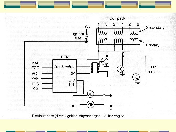
Distributorless Ignition PCM controls dwell and timing DIS module is like TFI module Also uses SPOUT l Now called Spark Angle Word (SAW) 1991 second generation using Reluctance instead of Hall sensors 35 teeth on crank 36 minus 1 for position
Distributorless Ignition Base Timing Check Remove SPOUT/SAW jumper l 10 o l Self check adds 20 o l Octane adjustment jumper looks like SPOUT l Retards 3 o to 4 o and can be left out
Spout Connectors
Idle Speed Carbs & CFI use Throttle kicker l DC motor idle speed control (ISC) l l Idle Tracking Switch l l Senses closed throttle PCM then operates ISC Act as Idle Dashpot
EFI Idle Speed Control Air bypass solenoid l. PCM Controlled l. Duty Cycle pintle l. Also a dashpot valve
Thermactor Air Management Thermactor Air Bypass (TAB) Thermactor Air Diverter (TAD) PCM Controlled
Thermactor Air Management CTS Below 50 o TAB grounded l Sends air to atmosphere Between 50 and 190 Bypass valve sends air to diverter and to manifold Over 190 closed loop and air goes to Cat Bypass at idle, WOT, and with failing O 2 S
Open Loop Tip The fastest way to see if vehicle is in open loop is to see where the air is going Cat = Closed Loop Atmosphere or manifold = Closed Loop Provided thermactor system is working
Canister Purge Three types Constant purge with no PCM controlled in-line solenoid PCM controlled with temperature controlled vacuum valve
Canister Purge/Heat Control To valve that warms intake manifold
EGR Control and EGR Vent 2 solenoids that are “dithered”
EGR Control EGR Shutoff Solenoid l l Uses one solenoid Controls ported vacuum EGR Shutoff Solenoid with Backpressure Transducer l l l One solenoid Strength of vacuum controlled by transducer Does not have EVP sensor
EGR Control Vacuum Regulator Introduced in 1985 and is used for most applications
EEC IV Diagnosis Codes follow self test Codes can be read l Manually Watch MIL l Hook up meter l Star II l Other scan tool l Notice the safety glasses
Slow and Fast Codes Slow codes can be read with pulsing meter or MIL Fast codes can be read by scan tool Fast codes precede slow and look like a momentary flashing.
Diagnostic Connector
KOEO Self Test Procedures Engine warm Turn off for 10 seconds KOEO, then ground STI Test will run, then read codes All accessories off 2. 5 L and 4. 9 L hold clutch fully in.
KOEO Self Test Codes
KOER Self Test Procedures Engine warm 2000 RPM 2 min Turn off for 10 seconds KOER, then ground STI Test will run, then read ID codes Push brake and turn steering wheel After code 10 (or 1 flash) snap WOT
KOER Self Test Codes
Computed Timing Pull SPOUT/SAW l Check for 10 o with timing light Reinstall SPOUT/SAW Run KOER self test l At end of last code, 20 o will be added to base timing for 2 min.
Other Tests Continuous monitor (wiggle) After last code, deactivate and reactivate self test l Wiggle wires etc. Fault will display l SEFI Cylinder Balance KOER after last code, tip throttle and release.