FOOD ENGINEERING DESIGN AND ECONOMICS PIPELINE DESIGN Design


 In a gate valve the diameter of the opening")


- Slides: 41
FOOD ENGINEERING DESIGN AND ECONOMICS PIPE-LINE DESIGN
Design of piping systems l l 1. 2. 3. 4. 5. 6. 7. 8. 9. The design of the piping system can influence the ease and cost of pumping very considerably. The following items should be considered by the engineer when developing the design for a piping system: Choice of materials and sizes Effects of temperature level and temperature changes a. insulation b. thermal expansion c. freezing Flexibility of the system for physical and thermal shocks Adequate support and anchorage Alterations in the system and service Maintenance and inspection Ease of installations Auxiliary or stand-by pumps and lines Safety a. design factors b. relief valves, flare systems
l l l For pipe-line systems there are some considerations; Thermal expansion and the resulting pipe stresses must be considered in any piping system design. Thermal expansions could easily cause a pipe or wall to buckle if the pipe is fastened firmly at each end without allowance for expansion. The necessary flexibility for the piping system can be provided by the use of expansion loops, changes in direction, bellows joints, slip joints and some other devices. The possibility of solidification can be handled by insulation, steam tracing and sloping the line to drainage valves. Water hammer may cause extreme stresses at bends in pipelines. These should be prevented not to damage piping systems. Liquid pockets should be avoided in steam lines through use of steam traps and sloping of the line in the direction of flow. Quick opening or quick closing valves may cause damaging water hammer and valves of this type may require protection by use of expansion or surge chambers. A piping system should be designed so that maintenance and inspection can be accomplished easily and precautions should be taken for the possible future changes. Personal safety considerations in the design depend to a large extent on the fluids, pressures and temperatures involved.
l Pipes are specified according to wall thickness by a standard formula for schedule number as designed by the American Standards Association, Ps: safe working pressure Ss: safe working stress Ten schedule numbers are in use at the present time. These are 10, 20, 30, 40, 60, 80, 100, 120, 140 and 160. For pipe diameters up to 10 in, schedule 40 corresponds to standard pipe and schedule 80 corresponds to extra strong pipe. Pipe sizes are based on the approximate diameter and are reported as nominal pipe sizes. Although wall thickness varies depending on the schedule number, the outside diameter of any pipe having a given nominal size is constant and independent of the schedule number. This permits the use of standard fittings and tools on pipes of different schedule number.
1. 2. 3. 4. 5. 6. piping system should be parallel and right angled turns should be used dismantling of the system should be easy for cleaning or changing some parts for ease of cleaning, spare connections should be present. (e. g. , tees or crosses should be substituted for elbows) if there is no pump and the flow is due to gravity alone, the pipe diameter should be greater than the required (also there should be few bends if possible) if there are valves, the possibility of leakage should be considered and precautions should be taken. the valve should be placed with taps directed upside and reached easily. there should be enough space for fully opened position of the valve.
Fittings l Ø Ø Ø Pipe fittings are the auxiliaries of the piping system and are used for the following purposes; To connect two pipes (nippels, couplings, flanges) To change the direction of flow (bends, elbows) To change the pipe diameter (concentric or eccentric reducers) Making connections with side parts (to tanks) To close one end of the pipe (plugs) To separate flow from main source to different lines (tee, cross, lateral)
coupling elbow nippel tee cross flange
Valves l i. ii. Despite the variety in their design, all valves have a common primary purpose; to slow down or stop the flow of fluid. Therefore valves can be divided into two broad classes Shut-off valves, with the purpose of to close off the flow Control valves, used to regulate flow. In all cases control or stopping function is done by placing an obstruction in the path of the fluid which can be moved inside the casing with little or no leakage of fluid to outside. Valves serve not only to regulate the flow of fluids but also to isolate piping or equipment for maintenance without interrupting other connected units.
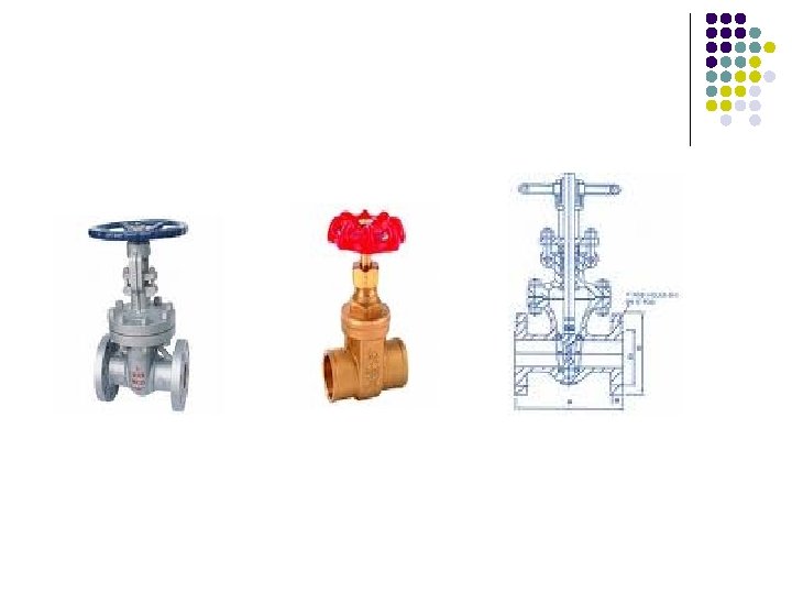
v Gate valves (slide valve) In a gate valve the diameter of the opening through which the fluid passes is nearly the same as that of the pipe and the direction of the flow does not change. As a result, a wide open gate valve introduces only a small pressure drop. The disk is tapered and fits into tapered seat. When the valve is open the disk rises into the bonnet, completely out of the path of the fluid. Gate valves work best when fully open or fully closed. Gate valves may have non rising stems, inside-screw rising stems or outside-screw rising stems. Rising stem valves require more space but the position of the stem visually indicates the position of the gate Gate valves are used to minimize pressure drop in the open position and to stop the flow of the fluid rather than to regulate it.
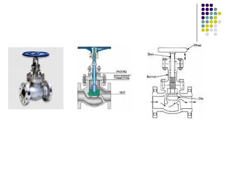
v Globe valves are widely used for controlling the flow rate of the fluid. In a globe valve the fluid passes through a restricted opening and changes direction several times. Globe valves are also designed as either inside screw rising stem or outside screw rising stem. Small valves are generally are of inside-screw type, while in larger sizes the outside screw type is preferred. In most designs the disks are free to rotate on the stems, this prevents galling between the disk and the seat. Globe valves in horizontal lines prevent complete drainage. This can be prevented by installing it with horizontal stem position.
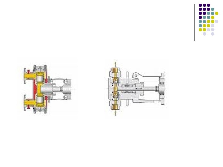
v Diaphragm Valves These valves are excellent for fluids containing suspended solids and can be installed in any position. The only maintenance required is replacement of the diaphragm which can be done very quickly without removing the valve from the line. Diaphragms are made of natural rubber, synthetic rubber or from natural or synthetic rubbers covered with Teflon® fluorocarbon resins. v Check valves A check valve permits flow in one direction only. It is opened by the pressure of the fluid in the desired direction. When the flow stops or tends to reverse the valve automatically closes. v Plug cocks These valves are limited to low temperatures since differential expansion between the plug and the body prevents functioning. v Ball valve In these valves on - off action is performed with one movement of valve arm. Although their use is easy, due to sudden closing water hammer may take place.
Diaphragm Valves Check valves Plug valves Ball valve
Pumps are used to transfer fluids from one location to another by increasing the pressure of the fluid and supplying the driving force necessary for flow. Power in form of electrical or steam energy may be transformed into mechanical energy which is used to drive the pump. Part of this mechanical energy is added to the fluid the as work energy and the rest is lost as friction due to inefficiency of the pump and the drive. The different types of pumps can be classified as l l l i. iii. iv. Reciprocating or positive displacement pumps Rotary centrifugal pumps Air displacement systems.
l i. ii. Ø Ø iii. Ø Ø Ø iv. v. vi. In pump selection the amount of fluid that must be pumped. the properties of the fluid the density and viscosity of the fluid influence the power requirement for a given set of operating conditions corrosive properties of the fluid determine the acceptable materials of construction if solid particles are suspended in the fluid, this factor determines the amount of clearance necessary and may eliminate the use of certain pump types. temperature, which in association with the vapor pressure of the liquid influences the possibility of cavitation. the increase in pressure of the fluid is due to the work input of the pumps. the head change across the pump is influenced by the inlet and downstream reservoir pressures the change in vertical height of the delivery line frictional effects as a major item in determining power requirement type of flow distribution type of power supply cost and mechanical efficiency of the pumps.
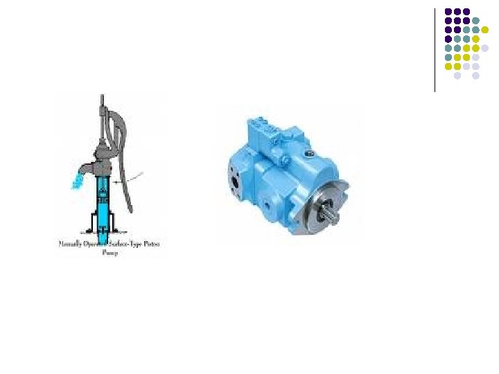
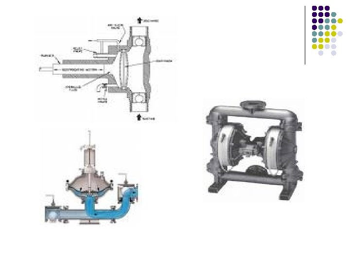
Reciprocating or positive displacement pumps l Piston pump The piston pump consists of a cylinder with a reciprocating piston connected to a rod which passes through a gland at the end of the cylinder. The liquid enters from the suction line through a suction valve and is discharged through a delivery valve. These pumps may be single acting or double acting. The theoretical delivery of a piston pump is equal to the total swept volume of the cylinders. The actual delivery may be less than theoretical value with volumetric efficiency greater than 90%. The piston pump can be directly driven by steam or electric motor. The piston type pump is comparatively simple in construction and operates with a high efficiency over a wide range of operating conditions. They can handle viscous liquids and develop high pressures. It can operate against a high head and does not require priming. However, delivery is uneven and presents an uneven load on the driving mechanism. Since with a well maintained piston pump the volume delivered is accurately known these pumps find use as metering pumps.
l Plunger pumps differ form piston pumps in that they have one or constant diameter plungers reciprocating through packing glands and displacing liquid from cylinders in which there is considerable radial clearance. They are always single acting in the sense that only one end of the plunger is used in pumping the liquid. Plunger pumps are available with one, two, three, four, five or even more cylinders. Simplex and duplex units are often built in a horizontal design. Those with three or more cylinders are usually of vertical design. The driver may be an electric motor, a steam or gas engine or a steam turbine.
Diaphragm pump The diaphragm pump has been developed for handling corrosive liquids and those containing suspensions of solids. These pumps perform similarly to piston and plunger pumps but reciprocating driving member is a flexible diaphragm made of metal, rubber, plastic or leather. The chief advantage of this arrangement is the elimination of all packing and seals exposed to the liquid being pumped. This is important for equipment required to handle hazardous or toxic liquids. The movement of the fluid is transmitted by means of the flexible diaphragm to the liquid to be pumped. The only moving parts of the pump that are in contact with the fluid are the valves and these can be specially designed to handle the material. l
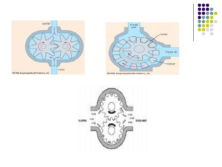
Rotary Positive Displacement Pumps Gear pumps are the most widely used of the positive action rotary pumps. Two gear wheels operate inside a casing. One of the gear wheels is driven and the other rotates in mesh with it. The impellers rotate with extremely small clearance between them and between the surfaces of the impellers and casing. The two gear wheels rotate in the casing, the suction connection is at the bottom. The pumped liquid flows into the spaces between the impeller teeth as these cavities pass the suction opening. The liquid is then carried around the casing to the discharge opening. Gear pump is a positive displacement pump and will deliver against high pressures. The delivery is almost independent of pressure and priming is not necessary. The main advantage of the gear pump over the reciprocating pump is that it gives an even delivery and can be directly connected to an electric motor drive. It will handle liquids of high viscosities, however, cannot be used for suspensions since the spaces between the gear teeth are comparatively small. l
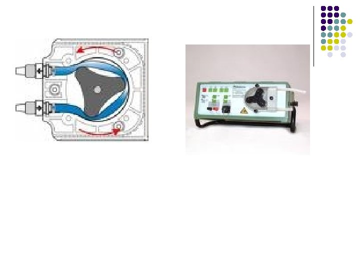
Peristaltic pump is a special form of pumps in which a length of silicone rubber or other elastic tubing is compressed in stages by means of a rotor. The tubing is fitted to a curved track mounted concentrically with a rotor carrying three rollers. As the rollers rotate, they flatten the tube against the track at the points of contact. These flats move the fluid by the positive displacement and the flow can be precisely controlled by the speed of the motor. These pumps have been particularly useful for biological fluids where all forms of contact ust be avoided. They are suitable for emulsions, creams and similar fluids in laboratories and small plants. These pumps may conveniently be used as metering pumps for dosage processes. l
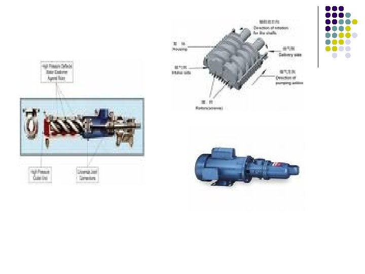
Screw pump A modification of the helical pump is the screw pump. In the two-rotator version in which he liquid is fed to either center or the ends, depending upon the direction of rotation, and progresses axially in the cavities formed by the meshing threads or teeth. In three-rotor versions, the center rotor is the driving member while the other two are driven. Screw pumps because of multiple arms that reduce slip are well adapted for producing higher pressure rises, especially when handling viscous liquids. l
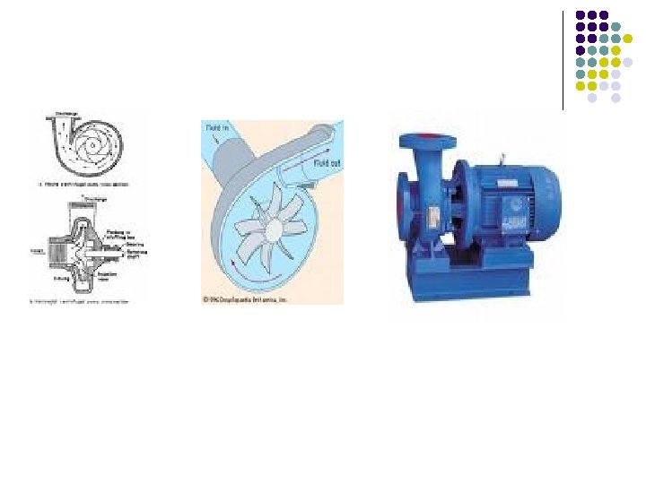
Rotary centrifugal pumps Centrifugal pump The centrifugal pump is the type most widely used in the processing industry for transferring liquids of all types (raw materials, materials in manufacture and finished products) as well as for general services of water supply, boiler feed, condenser circulation, condensate return etc. In this type of pump the fluid is fed to the centre of a rotating impeller and is thrown outward by centrifugal action. As a result of the high speed of rotation the liquid acquires a high kinetic energy and the pressure difference between the suction and the delivery sides arises from the conversion of kinetic energy into pressure energy. The impeller consists of a series of curved vanes so shaped that the flow within the pump is as smooth as possible. The greater the number of vanes on the impeller, the greater is the control over the direction of motion of the liquid and hence the smaller are the losses due to turbulence and circulation between the vanes. In the open impeller the vanes are fixed to a central hub, whereas in the closed type the vanes are held between two supporting plates and leakage across the impeller is reduced. In addition, the angle of the tips of the blades determines the operating characteristics of the pump. l
l l l A centrifugal pump will only operate effectively if a net positive suction head (NPSH) is available. These pumps require a minimum NPSH, which increases with flow rate, if cavitation is to be avoided. The pump manufacturers provide this data in a characteristic curve showing required NPSH versus capacity. To avoid cavitation the system must be designed so that the available NPSH exceeds the required value at the operating conditions. The available NPSH is given by the equation: Where, zs is the potential head on the suction side of the pump Ps is the pressure of the atmosphere on the suction side Pvp is vapor pressure of the liquid hfs is the head loss due to friction on the suction side ρ is the density of the liquid g is acceleration due to gravity
l When running at constant speed, the head developed by a centrifugal pump varies with the flow rate. At zero flow the pump head is maximum and as the rate of flow increases the head developed falls. This relationship for a particular pump is provided by pump manufacturers. Since system heads vary with the flow rate they must be calculated for different flow rates. These are also shown head versus capacity curves.
l The advantages of centrifugal pumps: 1. it’s simple in construction and can be made in a wide range of materials there is a complete absence of valves it operates at high speed and can be coupled directly to an electrical motor. In general, the higher the speed, the smaller the pump and motor for a given duty. it gives a steady delivery maintenance costs are lower than for any other type of pump no damage is done to the pump if the delivery line becomes blocked. it is much smaller than other pumps of equal capacity. liquids containing high proportions of suspended solids are readily handled 2. 3. 4. 5. 6. 7. 8.
l 1. 2. 3. 4. 5. The disadvantages of the centrifugal pumps the single stage pump will not develop a high pressure. multistage pumps will develop greater heads but they are much more expensive and cannot readily be made in corrosion resistant material because of their greater complexity. it operates at high efficiency over a limited range of condition. it’s not usually self-priming if a non-return valve is not incorporated in the delivery or suction line the liquid will run back into the suction tank. very viscous fluids cannot be handled efficiently.
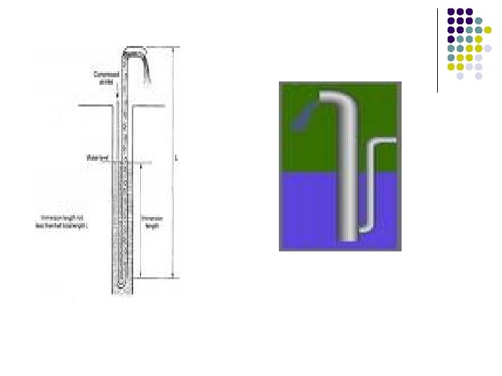
Air displacement systems All are based displacement of air with the amount of fluid to be transferred. l Air lifts Suction pipe is immersed in the fluid to be transferred and pressurized air is injected. Since no flexible parts are under the fluid level use is quite easy. l Acid eggs or blow cases These are closed systems where air inlet to the tank leads to controlled flow of fluid from the tank. They can be manual, automatic or semi-automatic. l Jet pumps In jet pumps fluid is passed through a nozzle, and with the pressure drop after the nozzle the fluid gets speed.
l l l l Comparison for pumps Positive displacement equipments in general, handle smaller quantities of fluids at higher discharge pressures than centrifugal equipments do. Positive displacement pumps are not subject to air binding and are usually self-priming. In both positive displacement pumps and blowers the discharge rate is nearly independent of the discharge pressure, so that these machines are extensively used for controlling and metering flow. Reciprocating devices require considerable maintenance but can produce the highest pressures. Rotary pumps work best on fairly viscous lubricating fluids, discharging a steady stream at moderate to high pressures. They can not be used with slurries. The discharge line of a positive displacement pump cannot be closed without breaking the pump, so that a bypass line with a pressure relief valve is required
l l Centrifugal pumps deliver fluid at a uniform pressure without shocks or pulsations. They run at higher speeds than positive displacement equipments and are connected to the motor drive directly through a gear box. The discharge line can be completely closed without damage. Centrifugal pumps can handle a wide variety of corrosive liquids and slurries.
l Overall mechanical energy balance for an incompressible fluid l Bernoulli equation where no mechanical energy is added and there is no frictional losses
l l l An optimum design is based on the best or most favorable conditions. In optimization studies critical stage is to determine what factor is to be optimized. (typical factors are: cost, profit, amount etc. ) In order to improve the quality of optimum design • • • objective constraints degrees of freedom is to be defined clearly.
l General procedure for solving optimization problems 1. Analyze the process itself so that the process variables and specific characteristics of interest are defined. (i. e. , make a list of all variables) Determine the criterion for optimization and specify the objective function in terms of the variables together with coefficients. Develop a valid model with mathematical expressions that relates the input-output variables of the process and associated coefficients. If the problem formulation is too large in scope; Break it up into manageable parts and/or Simplify the objective function and the model Apply a suitable optimization technique to the mathematical statement of the problem Check the answers and examine the sensitivity of the result to changes in the coefficients in the problem and the assumptions. 2. 3. 4. a. b. 5. 6.