Focal Plane detectors for Super Heavy Element research


")


: 1 μm thickness")

")
")

 Dynamic range:")


![Raw data (accumulated for 12 hours) Beam-like particles E [Me. V] 40 278113 30](https://slidetodoc.com/presentation_image_h2/d765db300a65a46ef7f32a22e18599c4/image-16.jpg "Raw data (accumulated for 12 hours) Beam-like particles E [Me. V] 40 278113 30")


![4000 [参考]BGS focal plane PH(Gamma) [chn] Si detector BOX ER 241 Am TOF detectors](https://slidetodoc.com/presentation_image_h2/d765db300a65a46ef7f32a22e18599c4/image-20.jpg "4000 [参考]BGS focal plane PH(Gamma) [chn] Si detector BOX ER 241 Am TOF detectors")


 TASCA (HTM) (SIM) DGFRS BGS RITU GARIS")


- Slides: 28
Focal Plane detectors for Super Heavy Element research RIKEN, Nishina Center Kouji Morimoto
RILAC Facility CSM Acc. Tanks RILAC Acc. Tanks RFQ-Linac 18 GHz ECR Ion Source
GARIS and GARIS-II Beam from RILAC GARIS-II GARIS Chemistry room GARIS-II GARIS 3
RIKEN GARIS(Gas-filled Recoil Ion Separator)
Focal Plane Detector system TOF 29. 5 α cm α SSD box ions 6 cm PSD
209 Bi + 70 Zn → 278113 36. 75 Me. V TOF 44. 61 ns 30. 33 mm + n 278113 a 1 st chain 23 -July-2004 18: 55 (JST) a 274 Rg 36. 47 Me. V TOF 45. 69 ns 30. 08 mm CN 278113 a 11. 68 Me. V (PSD) 344 μs 30. 49 mm a 11. 52 Me. V (PSD) 4. 93 ms 30. 16 mm 0. 88+10. 43=11. 31 Me. V (PSD+SSD) 270 Mt 34. 3 ms 29. 61 mm a a 2 nd chain 10. 03 Me. V 2. 32 Me. V (escape) 1. 136+8. 894(PSD+SSD) 1. 63 s 2 -April-2005 2: 18 (JST) 266 Bh 7. 163 ms 29. 45 mm 29. 79 mm a a 9. 08 Me. V (PSD) 9. 77 Me. V (PSD) Wilk et al. Phys. Rev. Lett. 85(2000) 2. 469 s 1. 31 s 9. 29± 0. 1 Me. V 0. 87 sec 262 Db 30. 91 mm 29. 65 mm s. f. 204. 05 Me. V(PSD) 40. 9 s 30. 25 mm 11. 15 Me. V 6. 149+5. 003 (PSD+SSD) 270 Mt 9. 260 ms 30. 40 mm 274 Rg CN s. f. 192. 32 Me. V(PSD) 0. 787 s 30. 47 mm Table of Isotopes T 1/2 34± 4 sec S. F. ~ 33% : α~ 64%
GARIS + gas-jet system Gas-jet coupled to GARIS as a pre-separator (Promising tool for next-generation SHE chemistry) 248 Cm(22 Ne, 5 n)265 Sg Preliminary H. Haba, H. Kikunaga, D. Kaji et al. , J. Nucl. Radiochem. Sci. , 9 27(2008). 7
Gas-jet transport system coupled to GARIS Mylar vacuum window (60 mmΦ): 1 μm thickness at 100 k. Pa Support grids: honeycomb (89%) or circle (72%) structure Chemically inert Teflon chamber: direct injection of chemical reagents Φ 60 mm Mylar window (Φ 60 mm) SUS chamber SHE atoms To chemistry apparatus GARIS Spacer (0, 30, and 60 mm) ~100 Pa 0 Honeycomb grid 100 mm He gas (+ aerosol) Gas-get chamber@GARIS
GARIS focal plane setup
Silicon detector Box TOF α α 6 cm PSD SSD box ions CANBERRA (PIPS) 58 x 58 mm 2 3. 75 mm x 16 strips, pad resistance 8 kΩ Depletion depth 300 μm Focal plane detector (Position sensitive PSD) Side detector
0 5. 5 6. 0 6. 5 7. 0 7. 5 Ea (Me. V) 7. 450 Me. V pn transfer 7. 837, 7. 897 Me. V 2 pn transfer 8. 088 Me. V 3 pn transfer 212 m. At 7. 679 Me. V 2 pn transfer 213 Rn 212 At 211 Po 7. 275 Me. V pn transfer 6. 775 Me. V 4 p transfer 209 Bi 8. 0 8. 426 Me. V 4 pn transfer 8. 546, 8. 478 Me. V 4 pn transfer 214 m. Fr 214 Fr 211 m. Po 300 213 Fr + 64 Ni evaporation residues 6. 281 Me. V a 3 n evap. 6. 383 Me. V 196 Po 6. 520 Me. V a 4 n evap. 199 At 6. 643 Me. V p 4 n evap. 200 197 Po 400 197 m. Po 6. 058 Me. V 6. 182 Me. V 198 Po 199 Po 100 5. 862 Me. V 140 Ce 200 Po Counts/10 ke. V Energy calibration of silicon detector + 64 Ni transfer products 8. 5 to GARIS 64 Ni 209 Bi 9. 5 Nat. Ce system check & energy calibration
Position resolution Escaped events from PSD Full deposited at PSD Position differences between 271 Ds implantation and sequential alpha-decays
Silicon detector box Detection Efficiency for decaying α particles: 85 % (Geometrical) Dynamic range: high gain 0 - 20 Me. V for α decay low gain 0 - 200 Me. V for spontaneous fission Pre Amp (Kumagai-san Amp): Cf=2 pf (Focal Plane PSD), Cf=3 pf (Side ) Shaping time: 2. 5 μsec Energy resolution: Focal Plane : 39 ke. V (FWHM) Focal plane + side : 66 ke. V Position resolution: read out up and down 0. 6 mm (10 Me. V α) For fast decay: 5μsec – Noise suppression: cooling 5 ℃ Dual ADC (2 nd gate)
To. F detector using thin mylar foil and MCP TOF 29. 5 α cm α 6 cm PSD SSD box ions Magnetic shield 磁気シールド 2つの役目: TOF測定 入射、崩壊イベントの区別
Time of flight detector Φ 80 mm Foil: 0. 6 μm mylar + Al 100Å + Cs. I 20 μg/cm 2 Wire: Φ 12 μm W+Au 2 mm pitch Timing resolution: for 241 Am α 530 psec (FWHM) Detection Efficiency: for 99. 9 % 241 Am Transmission efficiency ( two sets of detectors) 94 % (geometrical) Mass resolution A=270 で 約10 α
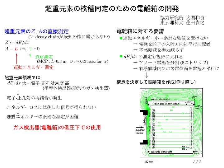
Raw data (accumulated for 12 hours) Beam-like particles E [Me. V] 40 278113 30 Target-like particles 20 10 0 0 Light charged particles 20 40 60 80 100 TOF [ns] Mass gate Counts 30 20 278113 10 0 10 1 Counts per 0. 01 Me. V 50 100 200 Mass 300 0. 3 cps 0 10 20 Total [ ROI = 8 - 12 Me. V ] 5 0 4. 2 x 10 -3 cps 8 9 10 11 12 Anti-coincidence with TOF detectors 6. 3 x 10 -4 cps 8 9 10 11 12 ER-α correlation (DP = ± 1 mm, Dt = 60 s) 5 0 0 Total (High gain) 8 a 4 a 3 9 10 a 2 11 Energy / Me. V a 1 12
Recent development and Future plans ○ Measurement of short life decay ( < 5μsec ) → measure the pulse shape of pre-amp signal using Flash ADC ○ αーγ measurement → Si + Cd. Te → Si + Ge ○ Large area focal plane detectors for GARIS-II → DSSD array → large area To. F detector using large area MCP ○ Improvement for mass measurement → Ion chamber
Short decay measurement PSD TOF Δt E 2 6 cm α α E 1 SSD box PSD rear Δt E2 E 1 Pulse shape Computer Pre. AMP Pulse height VME 16 strips Flash. ADC PSD front Shaping. Amp PH-ADC Signal processing diagram Pre. AMP CAMAC ions analysis
Recent development and Future plans ○ Measurement of short life decay ( < 5μsec ) → measure the pulse shape of pre-amp signal using Flash ADC ○ αーγ measurement → Si + Cd. Te → Si + Ge ○ Large area focal plane detectors for GARIS-II → DSSD array → large area To. F detector using large area MCP ○ Improvement for mass measurement → Ion chamber
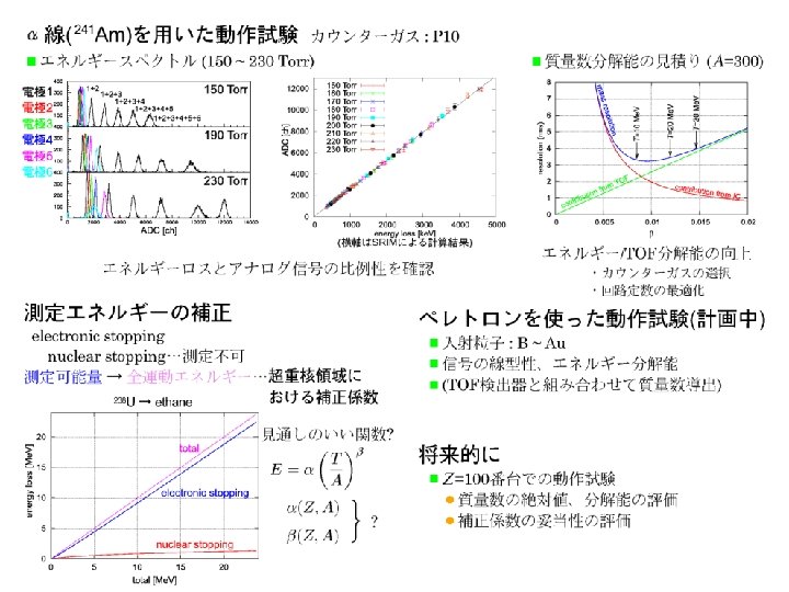
4000 [参考]BGS focal plane PH(Gamma) [chn] Si detector BOX ER 241 Am TOF detectors 1000 3000 59. 5 ke. V 500 2000 FWHM=2. 2 ke. V (for 60 ke. V γ-ray) 1000 0 ER TOF detectors 0 1000 8000 10 10 2000 3000 4000 PH(Alpha) [chn] Counts Si detector BOX 26. 4 ke. V 0 12001300140015001600 Si-Cd. Te array Acrorad製Cd. Te素子 10 mmx 1 mmt 1500 5. 48 Me. V Si-Ge array 5. 44 Me. V α-γmeasuremnt 67 ns decay 6000 4000 2000 0 0 100 200 300 TDC [chn] 400 500
Recent development and Future plans ○ Measurement of short life decay ( < 5μsec ) → measure the pulse shape of pre-amp signal using Flash ADC ○ αーγ measurement → Si + Cd. Te → Si + Ge ○ Large area focal plane detectors for GARIS-II → DSSD array → large area To. F detector using large area MCP ○ Improvement for mass measurement → Ion chamber
GARIS and GARIS-II Beam from RILAC GARIS-II GARIS Chemistry room GARIS-II GARIS 22
GARIS and GARIS-II Beam line GARIS GAR IS e m GA II SI R a Be lin GARIS-II commissioning March-2010 23
Comparison (GARIS-II vs. World working gas-filled RS) TASCA (HTM) (SIM) DGFRS BGS RITU GARIS DQh. Qv Qh. D Qv. DQh. Qv. D Length [m] 4. 0 4. 7 5. 8 3. 5 5. 1 Bend. Angle [deg] 23 25+45 25 45+10 30 30 30+7 Solid angle [msr] 8. 8 45. 0 10. 0 12. 2 13. 1 4. 3 20. 2 Bρ(max) [Tm] 3. 10 2. 50 2. 20 2. 16 2. 40 2. 43 Dispersion [mm/%] 7. 5 20. 0 10. 0 9. 7 9. 0 17. 7 Transmission [%] 41* 40* 60* 36* 75 Configuration 49 -59* ? DQh. Qv DQv. Qh GARIS-II Qv. DQh. Qv. D 238 U(48 Ca, 3 n)283112 Cross section Intensity Target thickness Transmission : 3 pb ** : 2 pu. A : 500 ug/cm 2 : 75% 3 atoms/day * M. Shaedel, TASCA workshop 2006 (2006). ** Yu. Ts. Oganessian et al. , Nucl. Phys. A 734, 195 (2004). 24
Development of GARIS-II focal plane detector TOF 29. 5 α cm α 6 cm PSD SSD box ions Large area To. F detector Large area silicon detector box DSSD: X: 60 strip, Y: 60 strip DSSD: 16 strip x 16 strip 70 mmφ → 120 mmφ Fine pitch (1 mm) : low capacitance 120 mm 60 mm 70 mm DSSD 120 mm Front: high gain ( 0 - 20 Me. V ) Rear: low gain ( 0 - 200 Me. V ) Read out: 60 x 8 = 480 ch.
Recent development and Future plans ○ Measurement of short life decay ( < 5μsec ) → measure the pulse shape of pre-amp signal using Flash ADC ○ αーγ measurement → Si + Cd. Te → Si + Ge ○ Large area focal plane detectors for GARIS-II → DSSD array → large area To. F detector using large area MCP ○ Improvement for mass measurement → Ion chamber