Foam Reinforced Aircraft Fuselage Study Narasimha Harindra Vedala


, “Bulging of Fatigue Cracks in a Pressurized Aircraft")


- Slides: 31
Foam Reinforced Aircraft Fuselage Study Narasimha Harindra Vedala, Tarek Lazghab, Amit Datye, K. H. Wu Mechanical And Materials Engineering Department Florida International University Miami, Florida
Overview v Propose a strategy to reduce the effect of fatigue failure v Simulate the failure behavior of fuselages due fatigue using finite element analysis Determine the effect of reinforcement on fatigue life due to the new proposed strategy v
Fatigue Failure It is defined as the failure of a metal structure due to cyclic loading. Fatigue Failure occurs at load amplitudes much lower than the breaking load of the material
Fatigue Failure in Aircrafts v Aging aircrafts fatigue analysis v Pressurization and Depressurisation of the fuselage results in cyclic stresses Aloha incident in 1988 caused due to fatigue failure
How to reduce the effect of fatigue failure? Using composite materials for manufacturing fuselages. Using Reinforcement to the fuselage Pantherskin Research on polyisocyanurate foam at FIU since 1988. Nicknamed as Pantherskin
Why Pantherskin? Inexpensive foam v Light weight : Density =2 to 4 lb/ft 3 v High fire resistance v
Fracture in metals Modes of Cracking in flat bodies (based on Linear Elastic Fracture Mechanics) Mode III
Objective Study the effect of adding foam layer to stress distribution in the fuselage v Generate a Finite Element model to conduct fatigue analysis on fuselage with foam reinforcement v Compare with results from previous methods v
Fracture parameters Stress Intensity Factors It is defined a quantity that characterizes the severity of the crack situation For flat plate with infinite width Strain Energy Release Rate E = Elastic modulus
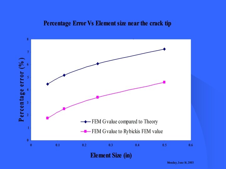
Verification study Procedure Verification Flat plate with central crack Results were compared with Rybicki’s (1977) model
Finite Element Analysis Model Definition Aircraft fuselage can be considered as a cylinder with equal spaced cracks Considering symmetric geometry a section of the fuselage is used for finite element analysis
Verification study : Unstiffened curved panel Procedure Verification Compared with Young’s model using STAGS FE package Longitudinal crack configuration
Bulging of crack in the fuselage
FEA of Aircraft Fuselage Boeing B 737 obtained Configuration R=74. 018 t= 0. 036 Aluminum EA=10. 5 Msi Foam EF =3000 psi v. A = 0. 33 v. F = 0. 3
Components of fuselage
Finite Element Model
Boundary Conditions and loading
Von Mises Stress
Stress distribution in the panel when 2 foam is added
Fatigue Analysis Coffin-Manson equation Strain range Cycles until failure. Slope of elastic strain amplitude vs. fatigue life. One reversal intercept of plastic strain vs. life line. On reversal intercept of elastic strain vs. life line. Slope of plastic strain amplitude vs. fatigue life
Fatigue Analysis Fuselage panel with Longitudinal Crack 4. 5
Global model and Submodel A submodel is generated to study the stress distribution near the crack Results for the global model are used for the nodes at the boundary of the submodel Location of submodel in the global fuselage panel
Von mises stress Distribution in Submodel
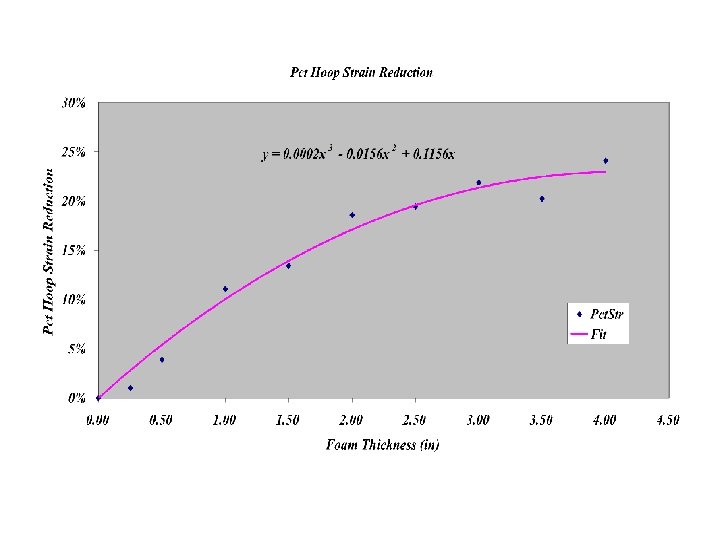
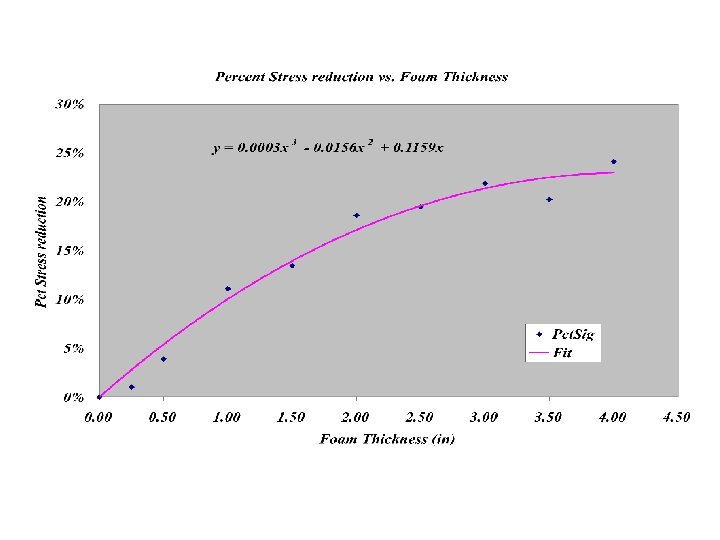
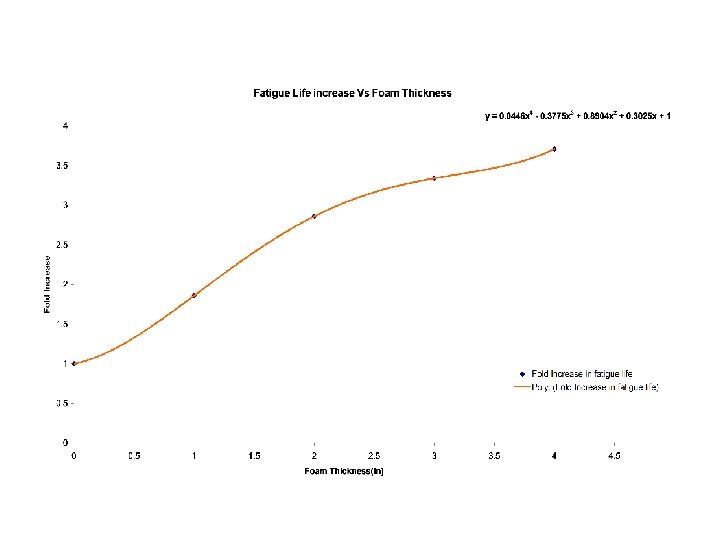
Conclusion Reinforcement of the fuselage skin with foam help to reduce the stresses distribution 18% for 2 " foam layer 25% for 4 " foam layer v A maximum of 32% reduction in stress intensity factor is possible for 4" foam addition v A 3. 7 fold increase in life of the aircraft is achievable if 4" foam is used v A parametric is developed which can be used for different fuselage configurations 1.
References • Chen, D. , (1991), “Bulging of Fatigue Cracks in a Pressurized Aircraft Fuselage, ” Ph. D. Dissertation, Department of Aerospace Engineering. Delft, The Netherlands: Delft University of Technology • Rybicki, E. F. , Kannien, M. F. , (1977) “A Finite Element calculation of stress intensity factors by a modified crack closure integral”. Engineering Fracture Mechanics, Vol. 9, pp. 931 -938 • Ahmed, A. A, Backukas, J. , Jr. and Paul W. Tan, Awerbuch J. , (2002) “Initiation and distribution of multiple-site damage (MSD) in fuselage lap joint curved panel”, Sixth Joint FAA/Do. D/NASA Conference of Aging Aircrafts, Albuquerque, San Francisco, CA. • Torres, M. J. and Wu, K. H. , (1993), “A New Approach to solve aging airplane problems using Polyisocyanurate”, Journal of Cellular Plastics, Vol. 29, N 4, p. p 380. • Rahman, A. , Backukas J. G. , Jr. , Paul W. Tan, and Catherine A. Bigelow, (2002), “Bulging Effects on longitudinal cracks in lap joints of pressurized aircraft fuselage”, Sixth Joint FAA/Do. D/NASA Conference of Aging Aircrafts, Albuquerque, San Francisco, CA.
Future Research Several modeling issues were encountered v Numerical formulation for defining fracture parameters for composite materials is not yet available v Results have to be verified by experimental tests v
Questions