FLYWHEEL BATTERIES Presented by 14 X 41 A

FLYWHEEL BATTERIES Presented by 14 X 41 A 0313 14 X 41 A 0314 14 X 41 A 0315 14 X 41 A 0316 14 X 41 A 0317 14 X 41 A 0318
 Main")
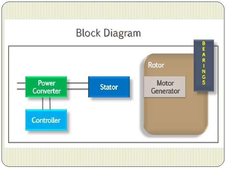
Contents • • • Introduction Flywheel technology Principles Block diagram Flywheel Energy Storage(FES) Main components Function and operation Stored energy Energy density Working of flywheel Applications Advantages

Introduction � A flywheel, in essence is a mechanical battery simply a mass rotating about an axis. � When short-term back up power is required the rotor’s inertia allows it to continue spinning and the resulting kinetic energy is converted to electricity. � They may still prove to serve us as an important component on tomorrow’s vehicles and future energy needs.

Flywheel technology �Integrates the function of a motor, flywheel rotor and generator into a single integrated system. �The motor, which uses electric current from the utility grid to provide energy to rotate the flywheel, spins constantly to maintain ready source of kinetic energy. �The flywheel rotor spin in a near frictionless environment, created by active power’s patented magnetic bearing technology.

Principles � The efficiency in the chamber is further enhanced by the creation of a rough vacuum, which reduces drag on the spinning flywheel. � As power is transferred to load, the flywheel’s speed decreases. Additional current is then supplied to the field coil to ensure that the voltage output remains constant throughout discharge. � This enables the flywheel system to provide ride through power during power disturbances.
 � FES works by accelerating a rotor to a very high")
Flywheel Energy Storage(FES) � FES works by accelerating a rotor to a very high speed and maintaining the energy in the system as rotational energy. � Advanced FES systems have rotors made of high strength carbon-fiber composites, suspended by magnetic bearings, and spinning at speeds from 20, 000 to over 50, 000 rpm in a vacuum enclosure. � Most FES systems use electricity to accelerate and decelerate the flywheel, but devices that directly use mechanical energy are being developed.

Main components � A typical system consists of a rotor suspended by bearing inside a vacuum chamber to reduce friction. � First generation FES system use a large steel flywheel rotating on mechanical bearings. never use carbon fiber rotor. � Magnetic bearings are sometimes used instead of mechanical bearings, to reduce friction.

Function and operation � Flywheel smoothen out variation in the speed of the shaft caused by torque fluctuations if source of driving torque is fluctuating. � It is also used to provide continuous energy in system. � It is also used to supply intermittent pulses of energy transfer rates that exceed the abilities of its energy sources.

Stored energy � Stored energy = sum of kinetic of individual mass elements that comprise the flywheel. Kinetic Energy = 1/2*I*� 2 where, I=moment of inertia i. e. , ability of an object to resist changes in its rotational velocity �= rotational velocity(rpm) I=K*M*R 2 (M=mass; R=radius) K=inertia constant(depend on shape)

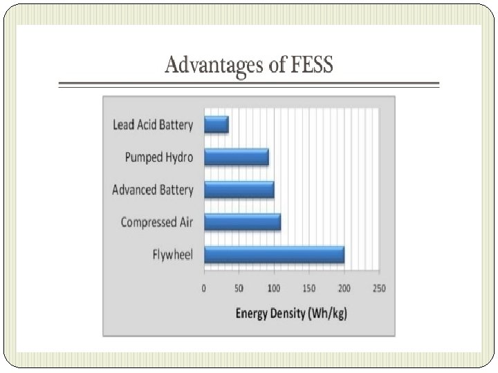
Energy density Ø The maximum density of a flywheel rotor is mainly dependent of two factors. 1. Rotor’s geometry 2. Property of Material used The relation is where, E - kinetic energy of the rotor [J] m - the rotor's mass [kg] K - the rotor's geometric shape factor [dimensionless] - the tensile strength of the material [Pa] - the material's density [kg/m 3]

Working of flywheel

Applications � Transportation � Uninterruptible power supplies � Laboratories � Aircraft launchers system � Pulse power � Grid energy storage � Wind turbines

Advantages � Provide continuous energy when energy source. � Flywheels have very high output potential and relatively long life. flywheel are relatively unaffected by temperature extremes. � The lifetime of the flywheel is almost independent of the depth of the charge and discharge cycle. � No periodic maintenance is required. � Short recharge time.

QUERIES?

THANK YOU
- Slides: 18