Fluoroscopy Review Notes From CDPH RHB Syllabus Rad

Fluoroscopy Review Notes From CDPH RHB Syllabus Rad Tech 244 - 2013

Fluoroscopy Notes Ch 1 • Approximately 5% of the US population has a fluoro procedure each year • The average number of fluoro exams person is 1. 3 • The average number of spot films is 4. 6

• The MC exam is a GI tract at 53% • A 2 minute UGI exam can produce an exposure ranging from 5 -15 rads, comparatively a KUB is between 100 -500 mrads. • Fluoro is defined as a rad exam utilizing fluorescence for the observation of the transient image.

• Fluoro was first used as a dynamic procedure. Second as a means of positioning for spot films. • Medical exposure accounts for about 20% of the total radiation people receive. • Even though the percentage is small, for medical exposure, it is the only exposure that is controllable. • FLUOROSCOPY TO POSITION PATIENTS IS PROHIBITED.

Notes Chapter 2 Factors Directly Affect Exposure • • • m. A k. Vp Collimation Filtration Exposure time – Total fluoro time • Target to panel distance (TPD) • Patient to II distance • Sensitivity of the image receptor – Essentially speed RSV

The following will reduce exposure • • • Collimating Last frame hold Shortest possible patient to II distance Highest possible k. Vp Pulsed fluoroscopy Using the largest II mode with collimation

Factors indirectly influencing exposure • Room illumination • Image receptor quality • Absorption of the table top

m. A • 0. 5 – 5 m. A – Usually 1 – 3 m. A • Spot films – 100 m. A or higher • Output and dose are directly proportional to m. A

k. Vp • • Maximum photon energy Beam quality Penetrability of the beam Tube potential

collimation • Required by law • Image quality improves as the beam is collimated

Collimation Collimate tightly to the area of interest. Ø Reduces the patient’s total entrance skin exposure. Ø Improves image contrast. Ø Scatter radiation to the operator will also decrease.

Factor affecting staff doses FIELD SIZE DEPENDENCE 100 k. V 1 m. A 11 x 11 cm 17 x 17 cm 0. 8 m. Gy/h 1. 3 m. Gy/h 0. 6 m. Gy/h 1. 1 m. Gy/h 0. 3 m. Gy/h 0. 7 m. Gy/h 1 m patient distance Patient thickness 18 cm Scattered dose rate is higher when field size increases 12

filtration • If the tube is operated above 125 k. Vp, 3 mm Al eq is required. • Filtration reduces patient dose

Source to table top target to panel distance • Cannot be less than 12” and should be 18” • Mobiles are required to be at least 12” • Fixed units, 15”

Patient to II distance • The closer the II, the lower the dose • This is more pronounced with fixed units. – Decreases the SID

• Tabletop – Less than 1 mm Al eq at 100 k. Vp • Exposure switch – Dead man type

Primary protective barrier • The II is the primary barrier and must have 2 mm Pb eq for systems operating above 125 k. Vp • The II has to be in place for the tube to energize

Protective Actions • Bucky Slot Cover – Automatically covered, 0. 25 mm Pb eq • Protective curtains – 0. 25 mm Pb eq – Not required on c-arms – Scatter at 1 foot can reach 500 mrad/hr

• Allowable exposure rates – Cannot exceed 5 rad/minutes • Unless, ABC or image recording • Cumulative timer – Cannot exceed 5 minutes • Illumination

II Considerations • Purpose – The basic purpose of the II is to make the fluoro image brighter – When the image is brighter it is easier to visualize structures • Brightness Gain – Minification gain multiplied by electronic (flux) gain

II Facts • Input phosphor, cesium iodide • Photcathode, danium antimony • Output phosphor, zinc cadnium sulfide

Image Quality Issues • Quantum Mottle – Caused by too few photons • Contrast – Subject – Detector – Image • Resolution

Effect of X ray Beam Penetration on Contrast, Body Penetration, and Dose t 23

Dose vs. Noise 2 µR per frame 15 µR per frame 24 24 µR per frame

• Distortion – Size, shape, pincushion • Lag • Vignetting – Less bright at the edges than center of image • Magnification tubes, Multi-mode – Variable Fo. V

Closed Circuit TV Systems • Camera – MC is the vidicon • Camera control unit – Video amplifier • Monitor – CRT, etc.

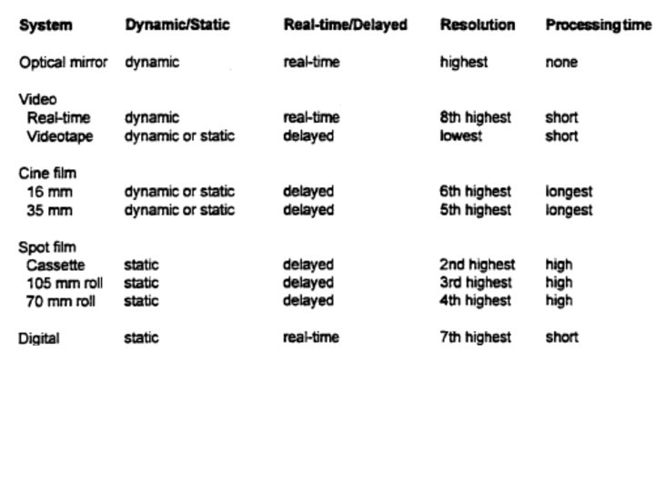
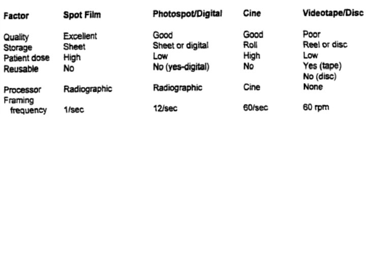
Cinefluoroscopy • Synchronization – Record with the x-ray pulses • Framing frequency – Division of 60 – The higher the rate the higher the dose • F-number • Video disk recording (electronic radiography) – Exposure ends when image is formed • Basically fluoro phototiming • 95% dose reduction

• Video tape – Instant playback and no additional dose • Spot films – Conventional cassettes – Photospot cameras • ½ to 1/3 dose of convent. Cass. • Lower image quality

Accessories • Gonadal shields – Required when possible • Grids – Fluoro uses low ratio grids • Cassettes • Cine film – Per frame basis 10 x the dose than fluoro

Factors affecting an Increase in Scatter • High k. Vp • Large field size • Thick body part

Advantages of 3 phase and medium/high frequency generators • Relatively high m. A • Higher effective k. Vp • Near constant potential – Less ripple

Notes for Chapter 3 • Fluoro Image Production • Fluoro units have 2 basic components – X-ray tube – Image intensifier

Fluoro X-ray Tube • Regular rotating anode x-ray tube • Runs at a lower m. A – Less than 5 m. A – Small focal spot • Possible because of the low m. A

II • The primary purpose is to increase the brightness of the fluoro image • Components – Glass envelope that provides a vacuum – Input layer • Converts x-ray photons to electrons – Electronic (electostatic) lens – Output layer

• Input layer – Converts x-ray photons to light photons – Light photons then strike the photocathode and convert into electrons – Electrons are then accelerated across the II – Electrons strike the output phosphor and are converted back into light photons
 I. I. Input Screen Electrode E 1 Electrode")
The image intensifier (I. I. ) I. I. Input Screen Electrode E 1 Electrode E 2 Electrode E 3 Electrons Path I. I. Output Screen Photocathode + 36

Image intensifier component * Input screen: conversion of incident X Rays into light photons (Cs. I) * * Photocathode: conversion of light photons into electrons * * only 10 to 20% of light photons are converted into photoelectrons Electrodes : focalization of electrons onto the output screen * * 1 X Ray photon creates 3, 000 light photons electrodes provide the electronic magnification Output screen: conversion of accelerated electrons into light photons 37

Image Intensifier Magnification Modes Same area Output phosphor Input Phosphor 9 inch field 6. 5 inch field
 RELATIVE PATIENT ENTRANCE DOSE RATE FOR SOME UNITS 12\"")
IMAGE INTENSIFIER Active Field-of-View (FOV) RELATIVE PATIENT ENTRANCE DOSE RATE FOR SOME UNITS 12" (32 cm) 100 9" (22 cm) 200 6" (16 cm) 300 4. 5" (11 cm) 400
 gain •")
Brightness Gain • BG is the product of minification gain and flux(electronic) gain • Minification Gain – Input phosphor dia. 2/output phosphor dia 2 • Making the image smaller will make it brighter. – The same number of photons are contained in a smaller area • In most IIs the output phosphor is 1 inch.

Flux Gain • Caused by the conversion efficiency of the output phosphor and the acceleration of the electrons across the II • As the electrons accelerate they gain kinetic energy • Flux gain is usually between 50 and 150.

Measuring Brightness Gain • The actual measurement is done by calculating the conversion factor – Intensity of output phosphor (candelas)/mrads/sec • Brightness gain will deteriorate 10% annually. – This will ultimately decrease image contrast

Beam Splitter Mirror • 10% of the output light goes to the vidicon (video camera) the remainder goes to the photospot device. • NOTE: not all units have a beam splitter

Vignetting and Pincushion Distortion • Pincushion – The loss of shape at the edges of the fluoro image • Vignetting – Loss of brightness at the edge of the image

Veiling Glare • Occurs when the light from the output phosphor ‘reflects’ back into the II. – Remember, the photocathode is stimulated by light, so light ‘reflecting’ from the output phosphor would also trigger electron production. – Decreased contrast results
 Automatic Brightness Control (ABC) • Keeps light output of the")
Automatic Brightness Stabilization (ABS) Automatic Brightness Control (ABC) • Keeps light output of the II constant. • Brightness of the image varies with changes to k. Vp and m. A. – Increase m. A increase brightness; direct relationship – Increase k. Vp 10% double brightness

Brightness Sensing • II photocathode current • Television camera signal sensing • Lens coupled phototube sensing

Types of ABS • Variable m. A, preset k. Vp – Set the k. Vp and the unit adjusts m. A • Variable m. A with k. Vp following – If the m. A range is exceeded the unit will automatically adjust the k. Vp to compensate • Variable k. Vp, preset m. A – Set the m. A and the unit adjusts k. Vp • Variable k. Vp, variable m. A

Closed Circuit TV Systems • Camera control unit – Power supply and video amplifier • Monitor

Cameras • Vidicon – MC, inexpensive, lag, 525 raster lines • Plumbicon – Cardiac cath labs – Fixed gain (better contrast) and low lag – Increased quantum mottle • Image orthicon – Not widely used • CCD – Solid state semiconductor – Small, low power consumption, low price, long life

Photoconductive camera tube Steering coils Photoconductive layer Focussing optical lens Deviation coil Alignement coil Accelarator grids Input plate Control grid Electron beam Iris Video Signal electrode Electron gun Field grid Electrode 51
 52")
Schematic structure of a charged couple device (CCD) 52

Monitor • 525 lines 30 times per second • Combined with the video camera improves image contrast

TV Image Quality • • • Horizontal resolution Vertical resolution Contrast Brightness Lag

• Horizontal resolution – Bandwidth or bandpass – Increase frequency bandwidth increase horizontal resolution • Vertical resolution – Determined by number of scan lines – Kell factor • Ratio of vertical resolution and scan lines

• Contrast • Brightness – Adjust contrast first and brightness after • Lag – Occurs when the II is moved rapidly.

Dynamic Image Recording • Video Tape – 2 advantages • Instant replay • No additional patient exposure – Disadvantages • Poor image quality, fixed frame rate,
")
• Cinefluoroscopy – 16 or 35 mm (MC high patient dose, better image) • Synchronization – Camera shutters open at the same rate as x-ray pulses • Framing rate • F-number – The lower the number the more light hitting the camera the lower the patient dose; however, more distortion at the edges

• Framing – Underframing should be avoided – Exact framing, diameter of the II fits in the shortest dimension of the film – Overframing, diameter of the II fits the largest dimension of the film. Part of the image is lost – Total overframing, diameter of the II is equal to the diagonal of the film
 (sticky fluoroscopy) –")
Static Image Recording • Video disk – Last image freeze (hold) (sticky fluoroscopy) – Electronic radiography, similar to AEC x-ray only until image is made. – Decrease dose up to 95% – 1 to 30 frames per second • Spot film • Conventional cassettes

• Spot film – Photospot • Image is taken from the II output phosphor • Dose 20 – 50 X higher per frame than fluoro because of higher m. A • Currently, 70 mm roll, 105 roll, 100 mm chip – 105 mm roll ½ the dose of cassette spots – Cassette spots • Slower ‘frame’ rate • Higher dose and better spatial resolution

Digital Fluoroscopy • Digital image is obtained from the output phosphor. – A vidicon then a digital image processor – Or, digital video camera • Digital photospot – Instant playback, possible image enlargement

Pulsed Fluoroscopy • Variable frame rates are possible with a corresponding decrease in patient dose
 fluoroscopy • Higher tube currents than normal – 10 -20 m.")
High level (boost) fluoroscopy • Higher tube currents than normal – 10 -20 m. A usual 40 m. A potentially – Increase patient dose 2 -10 times reg. Fluoro – 10 -50 rads per minute – Limited to 20 rad/minute unless recording the image • Key points – Special activation required, audible signal, dose rate limited to 20 rad. minute

Notes from Chapter 4 Conducting the Fluoro Exam • Operator dose is directly proportional to patient dose • Image brightness is directly proportional to dose rate at input phosphor

Technical factors which directly influence dose rate at the table top • • • m. A k. Vp Collimation Filtration Exposure time Target panel distance

Technical factors which indirectly influence dose by affecting technical factors • Room lighting • Image receptor quality • tabletop

Collimation • A border needs to be visible when the II is 14 inches above the tabletop and the collimator is fully opened • With an automatic collimator, a border should always be visible • Image is not brighter with a less collimation (bigger field size)

Filtration • Total filtration – 2. 5 mm Al eq < 125 k. Vp – 3. 0 mm Al eq at 125 k. Vp and above • Total filtration includes inherent and added • Exposure rate should be less than 2. 2 rads/min at 80 k. Vp • HVL

Allowable exposure rates • Limited to 5 rads per minute • If the unit has ABC/ABS then 10 rads/minute is allowed – However, if the unit has ‘boost’ then the limit is 5 rads/minute • ABC/ABS units have to be checked by a physicist annually – Also have to have weekly fluoro checks of m. A and k. Vp – No ABS 3 year check by physicist

TPD • TPD increases from 12 to 18 inches – Pt. Dose decreases by 30% • II as close as possible to the patient

Room Lighting • Affects visual acuity – Photopic acuity is 10 X better than scotopic acuity – Day versus night vision • Normal viewing distance is 12 – 15 inches • Image recognition in 0. 2 seconds

Gonadal Shields • 0. 5 mm Pb eq • 97% effective at 100 k. Vp and 3 mm Al filtration

Notes from Chapter 5 Basic Operational Procedures • Minimize exposure time by utilizing short looks • Use the cumulative timer • Use the highest applicable k. Vp • Collimate • Use mag and boost only when necessary • Use last image hold

• • Use a photospot instead of cassettes Use video tape Use II with good contrast Monitor the TV monitor for brightness and contrast • Minimize the pt. II distance • Position the II prior to exposure

• Prevent pt. Motion with instructions • Use gonadal shielding when possible • Use compression devices

Factor affecting staff doses ANGLE DEPENDENCE 100 k. V 1 m. A 0. 9 m. Gy/h 0. 6 m. Gy/h 11 x 11 cm 0. 3 m. Gy/h 1 m patient distance patient thickness 18 cm Scattered dose rate is higher near the area into which the X -ray beam enters the patient 79

Factor affecting staff doses DISTANCE VARIATION 100 k. V 1 m. A 11 x 11 cm m. Gy/h at 0. 5 m m. Gy/h at 1 m Scattered dose rate is lower when distance to the patient increases 80

Factor affecting staff doses X-Ray tube 100 k. V 1 m m. Gy/h 2. 2 (100%) 2. 0 (91%) 20 x 20 cm 1. 3 (59%) Tube undercouch position reduces, in general, high dose rates to the specialist’s eye lens m. Gy/h 1 Gy/h (17 m. Gy/min) 1. 2 (55%) 1 m patient distance 1. 2 (55%) 1 Gy/h (17 m. Gy/min) 1. 3 (59%) 20 x 20 cm 100 k. V 1 m 2. 2 (100%) 1 m patient distance X-Ray tube 81

Mobile Concerns • • • Audible indicator Cumulative timer visible on the monitor Video storage Last frame hold Longest possible TPD

Notes for Chapter 6 Pediatric Fluoroscopy • Motion – Sedation – Mechanical devices • Personnel and Parental Protection – Everyone in the room needs lead • Gonadal shielding • Artifacts

• ABS/ABC – Watch putting the II directly over large concentrations of contrast • Distance • Collimation • Photospots instead of cassette spots if possible

Notes for Chapter 7 Mobile Fluoroscopic Equipment • Primary beam is intercepted by the II – If the II is used routinely in a single location it needs to have secondary shielding • SSD has to be at least 12 inches • Must have an II • Collimation has to be used or unit will not energize • Unit cannot energize unless the II is in the primary beam

• Maximum dose rate of 5 rads/minute • Personnel monitoring in required for all persons operating fluoro equipment • Protective aprons are required if exposed to more than 5 mrads/hour • Boost mode should only be used after areas of interest have been localized

Notes for Chapter 8 Responsibilities of X-ray Supervisor • Chief Radiologist or designees are responsible • Licentiates who can use and supervise fluoro – Radiology supervisor and Operator – Fluoro supervisor and Operator • Techs with Fluoro permits can only use fluoro when supervised by above

Specific requirements • • • Establish a fluoro procedures manual Annual review of manual Assure that techs don’t practice medicine Observe tech performance Assure techs are offered training Assure equipment monitoring is adhered to

Personnel Protection • Operator is adequately protected from scatter • Individuals in the room need to wear aprons and film badges • Use protective devices as applicable

Protection Devices SCREEN AND GOGGLES CURTAIN THYROID 90

Restrictions • Techs can only use fluoro equip. under the supervision of a supervisor operator • Techs cannot interpret films • Techs cannot use a title implying the right to practice medicine
 – Total dose")
Notification Requirements • Immediate notification (prompt phone call and timely letter) – Total dose 25 rems – Eye dose 75 rems – Skin or extremity dose of 250 rems • 24 hour notification ( call within 24 hours and a letter follow-up) – Total dose 5 rems – Eye dose 15 rems – Skin or extremity 50 rems

Notes on Chapter 9 Supervision of Techs w/Fluoro permits • • • Clear the room of unnecessary personnel Collimate Use shields Use correct technical factors Position the patient correctly Avoid patient motion

• Direct supervision – Use equipment only as trained • Indirect supervision – Spot filming and video taping

Notes on Chapter 10 Health Effects of Low Level Radiation dose • Somatic dose indicators – Injuries to superficial tissue – Induction of cancer – Cataracts, fertility issues, life-span shortening – Injuries to developing fetus • Based on dose at specific locations or points

• High marrow dose exams – BE, UGI, abdominal angio • Genetic dose indicators – 50 rads temp male sterility – 30 rads temp female sterility • Genetically significiant dose – Number of future kids – X-ray exam rate – Mean gonadal dose/exam

Notes on Chapter 11 Biological Effects and Significance of Dose • Effects appear to follow a linear nonthreshold dose curve – Dose rate to tissue – Total dose – Type of cell exposed

Radiobiological injury • Cellular amplification • Gross cellular effects – MC effect is the cessation of cell division • Latent Period – Short term, weeks or less • Immediate or early effects – Long term, years or longer • Delayed or late effects

Dose relationship curves Threshold Non-linear Non-threshold linear Regulations are based on non-threshold linear curves

Variations in Cell Sensitivity • Bergonie and Tribondeau – Number of undifferentiated cells – Degree of mitotic activity – Duration of active proliferation • Radiation induced mitotic delay is usually reversable

Cell Sensitivity • • • Lymphocytes or white blood cells RBCs Epithelial Endothelial Connective tissue cells Bone Nerve Brain Muscle

Short Term Effects • 25 rads or less demonstrate no effects

Long Term Effects • No specific effect associated with radiation exposure • Somatic damage – Increased incidence of cancer – Embryological effects – Cataracts – Life span shortening • Genetic mutations

Carcinogenic Effects • Human evidence – Early radiologists and dentists – Radium dial painters – Uranium miners – Survivors of Hiroshima and Nagasaki

Radiation Induced Cancers • • • Female breast Thyroid Hemopoitic tissue Lungs GI tract Bones

Embryological Effects • As little as 10 rads demonstrates effects in animal models • 50 rads can cause spontaneous abortion

Notes on Chapter 12 Personnel Radiation Protection • ALARA • Basis for radiation protection requirements – Stochastic effects • Probability of an event occurring, ie cancer – Non-stochastic effects (deterministic) • Severity of the effects varies with exposure

Operator Exposure • Distance • Apparel – Aprons, 0. 25 mm Pb 97% effective • 0. 5 mm Pb, 99. 9 % effective • Should be placed on hangers when not in use • Aprons cover 80% of the bone marrow

Notes on Chapter 13 Personnel Monitoring • • Record exposure Measure accumulated exposure Indicate type of exposure Provide a record of exposure

Types • Film badge – 10 mrad to 700 rads – +/- 25% accuracy • TLD – Lithium fluoride – +/- 9%, cannot be reread • Others – Pocket dosimeter – Audible device

Maximum Permissible Dose For adults over 18 y/o • Whole body - head, trunk, arms above the elbow, and legs above the knee – 5 Rem • Skin and extremities – 50 rem • Lens – 15 Rem • Occupational dose for people under 18 y/o 10% of adult dose

Occupational Exposure Limit Whole Body – 5 rem/year Extremities – 50 rem/year Eye – 15 rem/year Pregnant workers – 0. 5 rem/gestation period General public Limited to 0. 1 rem/year (Addition to the background radiation) 0. 002 Rem (2 mrem) per hour

Who must be monitored? • Persons in high radiation area – 0. 1 Rem per hour at 30 cm – Fluoro rooms • Persons operating mobile x-ray equipment • Radiation Area – 0. 005 Rem per hour at 30 cm

Typical Exposures mrem/yr 5000 4000 3000 2000 1000 0 MPD Cardio. Pain Mgnt. X-Ray Tech
- Slides: 114