FLUOROSCOPY RADIATION SAFETY Presented by Dr Kish M

FLUOROSCOPY RADIATION SAFETY Presented by Dr. Kish M. Patel, DABR

In the Radiology Department, you will be in close proximity to various types of radiologic equipment including Fluoroscopy which uses x -rays to produce dynamic images of internal moving body parts. This presentation will guide you in set up and the environment of fluoroscopic areas and instruct you on radiation safety for yourself and your patient. 2

EVOLUTION OF FLUOROSCOPY Historically, early fluoroscopy units did not look anything like what they are today. Invented by Thomas Edison, they were hand-held devices that “glowed” or fluoresced an image when they were exposed with an x-ray. 3

The unshielded x-ray tube would project unfiltered x-rays through the body part that you wanted to visualize. It exposed not only the body part, but blasted the face and eyes of the operator with harmful radiation. This frequently lead to skin erythema to the patient and cataracts to the holder of the fluoroscope. 4

Fluoroscopes were also used for non-medical applications. Shoe-fitting fluoroscopes were invented to see how well new shoes fit. Installed in shoe stores in the U. S. through the 1970's, buyers would stick their feet into the hole at the bottom of the device to see if their new shoes fit properly. 5

Fluoroscopic units are still being used today in other consumer applications, the most common being luggage inspection systems. Because these devices are so heavily shielded, radiation exposure to the operators and the general public is minimal. 6

As technology evolved other fluoroscopic equipment was developed. This image shows a stand-holder for the fluoroscopic screen. This image shows a radiolucent x-ray table that could recline or elevate as desired. 7

In 1953, the first image intensifier was developed by a company called Fluorex. With early fluoroscopic devices, the images were too dim and operators had to work in complete darkness to even see the image. 8

These are modern fluoroscopy systems. Current systems project the images to hanging monitors so everyone in the room can see them. 9

FLUOROSCOPY COMPONENTS Fluoroscopic Imaging Chain 10

Fluoroscopy Suite Equipment 1 - Flat panel monitors 2 1 3 2 - Radiographic X-ray tube. This produces static (still images). 3 - Fluoroscopic image intensifier which, depending on the angulation of the table, would be located either above the patient or in front of the patient. 4 - Fluoroscopic X-ray tube under the 4 radiolucent table. In the table’s horizontal position, the x-ray beam would project up through the patient. It would be intercepted by the image intensifier which would then “intensify” the image and send that amplified signal to the monitors. 11

IMAGING APPLICATIONS Fluoroscopy The most common application is in the Radiology Department. These fixed devices are used for dynamic imaging of moving body parts such as visualizing contrast media flowing through the GI tract. 12

C-arm Mobile C-arms allow for imaging to go to the patient, such as sedated patients in surgery. Additionally, C-arms are capable of rotating around a patient in different planes. Combining motions creates an almost infinite number of potential projections of body structures which allows physicians a clearer view of their region-of-interest. 13

The most common application for C-arm use is the operating room. Due to sterile conditions, a C-arm has the flexibility to rotate around the patient while covered and will not contaminate the sterile field. Fluoroscopic images are essential for orthopedic surgeons in repairing broken bones, neurosurgeons performing delicate brain and spinal cord procedures, as well as various other applications. 14

Cardiac catheterization labs use C-arms to image the chambers of the heart and their associated coronary vessels. Angiography suites image the rest of the blood vessels of the body. Cardiologists use fluoroscopic-guided imaging to help properly place pacemakers and otherapeutic devices in the circulatory system. 15

When using C-arms, biplane imaging is beneficial. This utilizes 2 C-arms aligned in different planes. With a single plane C-arm, an exposure is made in one projection and then the C-arm must be rotated to make the second projection. This increases surgical time and amount of time the patient is sedated. 16

MEDICAL RADIATION EXPOSURE Fluoroscopy and CT imaging modalities are large contributors to the increase in medical radiation exposure. The national Image Gently and Image Wisely campaigns recommend, whenever possible, replacing these exams with lower or non-ionizing modalities such as Diagnostic X-ray, MRI or Sonography. 17

Acute skin injury can occur with fluoroscopic procedures. Effects are dose dependent and generally occur within 30 days of exposure. Erythema, which resembles sunburn, appears within few hours to a few weeks and fades in hours to days. If the dose is sufficient, epilation occurs at approximately 2 -3 weeks. Changes may then progress to dry or moist desquamation. Dry desquamation consists of dry, scaly skin. Moist consists of blistering and sloughing with weeping of serous fluid. Approximately 1 month from exposure, dermal necrosis may occur. Wounds can heal with appropriate care, but can recur or progress to chronic. 18
 atoms. • In")
Biological Effect of Radiation • Radiation ionizes (knocks off electrons from) atoms. • In the human body, mostly it ionizes water. • The ionized water breaks up into radicals that break DNA chains. • If left alone long enough, a broken DNA chain can repair itself. No harm done. • If the cell divides before the chain repairs itself, the cell dies. • Enough cells die and bad things happen. • Cells die when they divide too fast to repair themselves or when the radiation is coming in too fast to give them a chance. 19
 Slowly dividing cells (least sensitive) Sperm")
Radiation Sensitivity • Rapidly dividing cells (most sensitive) Slowly dividing cells (least sensitive) Sperm Lymphocytes small intestine Stomach Bone Skin Nerves Colon • • 20

The Nature of Radiation Damage • Radiation damage seldom appears at the time of irradiation. • Visible effects occur later, from several hours to nearly a year. • The first (almost) visible effect is a drop in the white blood count. • The first external visible effect is a skin burn or rash. 21

Radiation Therapy • Cancer cells divide much more than normal cells. • Radiation kills both normal and cancer cells, but the cancer cells have less opportunity to repair themselves. • Repeated applications of radiation eventually kill all of the cancer cells while the normal cells recover. 22

Radiation Damage • Stochastic effects • Amount of radiation determines probability of effect • Once it happens the effect does not improve when the radiation is taken away • Death is the ultimate stochastic effect • Non-stochastic effects • Amount of radiation determines severity of the effect • When the radiation is taken away the effect improves • Skin burns are most common non-stochastic effect 23

More Radiation Damage • Effects show up days or weeks later depending on how much radiation was used. • The more radiation, the quicker the effect appears. • Patients may not associate a square sunburn with the heart cath they had three weeks ago. • It’s up to the physicians to be alert for late effects of radiation. 24

What’s Possible. . . With Fluoro’ • The maximum output of a fluoroscope is limited by law to 10 R/min at the patient’s skin surface (20 R/min on boost mode). • At that rate skin reddening can occur after about 20 minutes of fluoro (10 minutes on boost mode). • At more typical rates reddening can occur with about 50 to 200 minutes of continuous fluoro time. • Ciné (a fluoroscopy movie) is taken at high—and not limited—rates. Skin burns can occur in as little as 2 minutes of fluoro. 25

RADIATION PROTECTION ALARA: principle of reducing radiation exposure As Low As Reasonably Achievable https: //www. youtube. com/watch? v=Jf. QP 2 uv. QI 94 The cardinal rules: • Time - decrease • Distance - increase • Shielding – wear / position Highest priority is protecting the patient and medical personnel working in the fluoroscopy area. Only essential personnel should remain while fluoroscopy is active. Medical caregivers and family members will be provided protective shielding prior to engaging the fluoroscopy unit. 26

Some Ugly Picture • 49 -year-old woman with 8 -year history of refractory supraventricular tachycardia. • Sharply demarcated ulceration above elbow 5 months after radiofrequency cardiac catheter ablation. 27

• 56 -year-old man with obstructing lesion of right coronary artery. • Posterolateral chest wall at 10 weeks after percutaneous transluminal coronary angioplasty shows 12 x 6. 5 cm hyperpigmented plaque with hyperkeratosis below right axilla. 28

• Skin wound caused by an estimated 2 hours of fluoroscope time during coronary angioplasty. • The first symptoms appeared six to eight weeks after the procedure. The wound appeared to heal spontaneously and then reappeared. This photograph was taken 18 to 21 months following the procedure. 29

Patient Dose • Only a small portion of the radiation from a fluoroscope makes it to the II. • The rest stays in the patient. This energy is the patient dose. • The patient dose is responsible for damage to a patient’s skin or increase in cancer risk. • Step on the pedal and the machine automatically adjusts the k. V and m. A to give a good image. • As you move the fluoroscope around the k. V and m. A automatically adjust. 30

Technique Factors The technical factors of k. Vp and m. As are used to select the energy needed to generate x-rays. By increasing k. Vp, higher energy x-rays are generated which result in increased penetration and less absorption by the patient. This equates to a reduction in patient radiation dosage. When m. As is decreased, less x-rays are generated which result in a decreased amount being produced and absorbed by the patient. This equates to a reduction in patient dosage.

Magnification and Field of View Input Phosphor Output Phosphor Radiation dose is affected by magnification mode. The input phosphor captures the x-ray beam and after several conversions minifies and concentrates an image onto the output phosphor. Larger input phosphor = more light concentrated on the output phosphor. A smaller field size would magnify the image, but would not produce as bright of an image. Therefore, the X-ray generator has to produce more k. Vp and/or m. As to compensate and increases the patient’s radiation dosage. 32

Collimation 33
 When using fluoroscopy, it is preferred that the image")
Short Object Image Distance (OID) When using fluoroscopy, it is preferred that the image intensifier be positioned as close to the patient as possible and x-ray tube as far from the patient as possible. Patient dosage is significantly reduced and there is better image detail. 34
 is large, periodically change the entrance")
Changing Entrance Port Even if the region-ofinterest (ROI) is large, periodically change the entrance port. By doing this, radiation is not concentrated to a single spot and is distributed more evenly. 35

Pulsed Fluoroscopy Instead of using a continuous radiation exposure, pulsed fluoroscopy allows for exposures that are broken down into 130 pulse/second. Additionally, pulse length can vary anywhere from 5 -20 milliseconds/pulse. This decreases radiation exposure to the patient. 36

Cine/Digital Mode • Similar to regular fluoro’ mode, i. e. continuous or pulsed • The current is much higher up to >20 times greater • The dose rate is proportionally higher • Maybe >100 R/min c. f. 5 -10 R/min for regular • Image quality is much better • A continuous verbal “beep” or “tone” is heard • Should only be used when absolutely required • And only for a few seconds at a time 37

Grid Controlled Fluoroscopy Grid-controlled fluoroscopy x-ray tubes allow for very short exposures with very little scatter radiation. Combined with pulsed fluoroscopy, this can produce a crisper looking image with minimal scatter radiation. 38

Additional Patient Protection Lead Shield • Shielding is especially important for pediatric patients whose bodies are still developing. Reminder: shielding needs to be between the x-ray tube and patient (x-ray tube is under the patient in the image above). • Certain pathologies make the patient more radiosensitive, such as connective tissue diseases. Unnecessary fluoroscopy exposure can increase the likelihood of an adverse reaction. 39

Occupational Protection Fluoroscopy Of the cardinal rules of radiation protection, distance is the best protector. Stepping back one step from the source of radiation can reduce radiation exposure by a factor of 4. As you can see even with fluoroscopy drapes or curtains installed, the scatter field radiates past the superior and inferior ends of the table with the highest amounts of scatter in the A, B, & C regions. 40

Occupational Protection C-arm Mobile fluoroscopic C-arms do not have protective drapes or curtains; therefore, the operators and other occupants of the room are being exposed to a much wider scatter field. It is best to stand on the image receptor side of a C-arm because the majority of scatter radiation is on the x-ray tube side, the patient will absorb a large portion of the x -ray beam and the x-ray beam is collimated down to the size of the image receptor. 41

When the C-arm is tilted away from the operator, the scatter coming off of the patient and image intensifier radiates laterally exposing more of the operator’s face and neck. However, when the C-arm is tilted towards the operator the image intensifier itself becomes a primary barrier to facial exposure and the legs and feet take the brunt of the radiation exposure. 42

Protective Apparel Protective apparel is required for all persons who are in the vicinity of fluoroscopic exposure. Wearing a lead apron is essential. If it is not the wrap-around style apron, the wearer must be aware of exposing their unprotected back. Lead gloves need to be used if an operator must place their hands within the x-ray beam. With the radiosensitivity of the thyroid gland, wearing a lead thyroid shield is important in protecting that organ. 43

RADIATION PROTECTION SUMMARY • • • • Collimate the x-ray beam Select the highest k. Vp & lowest m. A to obtain optimal image Use additional beam filtration Keep the image intensifier close to the patient Change entrance port Use large field-of-view and limit the time using magnification mode Depend more on last-image hold rather than live fluoroscopy Select pulsed fluoroscopy Shield patient & caregivers Follow the 3 cardinal rules of ALARA: decrease time, increase distance, shielding Only essential personnel in the room Utilize protective apparel Position yourself closer to the image intensifier with mobile C-arm Step back when possible and stand behind another shielded person 44

Patient Safety Issues • Fluoroscopic techniques are being used by an increasing number of clinicians not adequately trained in radiation safety or radiobiology; • Patients are suffering radiation-induced skin injuries due to unnecessarily high radiation doses. Younger patients may face an increased risk of future cancer; • Many fluoroscopic users are not aware of the potential for injury from procedures, their occurrence or the simple methods for decreasing their incidence utilizing dose control strategies; 45

Patient Safety Issues • Many patients are not being adequately counseled about radiation risks before consent for difficult and challenging procedures, nor followed up for the onset of injury, when radiological procedures result in high doses; • If fluoroscopists are untrained or inexperienced can result in injury to patients and expose staff to high doses. • Occupational doses can be reduced by limiting unnecessary patient dose, through the correct use and procurement of equipment (including the use of shielding devices). 46

The Ten Commandments 1/ Dose rates greater for heavier patients 2/ Minimize current, m. A, & raise k. Vp to optimize I/Q 3/ Maximize tube-patient distance 4/ Minimize patient-intensifier distance 5/ Minimize geometric & electronic magnification 6/ Use of grid, m. A, dose, so I/Q 7/ Collimate beam 8/ Personnel shielding & dose monitoring 9/ Minimize beam-on time 10/ Maximize personnel distance from primary beam

Units of Radiation Exposure Only in air Dose In tissue Effective Dose In tissue Old Units New Unit Roentgen R & m. R Air Kerma (None) Rad rad & mrad Gray Gy & m. Gy Rem rem & mrem Sievert Sv & m. Sv 48
 or Roentgen }")
Units of Radiation • How much is there? { m. Gy(a) or Roentgen } • DEFINED ONLY FOR X-RAY • X-RAY IMPARTS KINETIC ENERGY TO ELECTRONS OF ABSORBING MEDIUM • EXPOSURE (R) MULTIPLIED BY X-RAY BEAM AREA (CM(2)) IS Dose Area Product 100 R = 1 Gy(a) 1 R = 10 m. Gy(a) Typical Fluoroscopic output rate 5 R/min (at patient skin entrance, ESE) Typical Cine (Digital) output rate 30 -70 R/min (at patient skin entrance, ESE) 49
")
Units of Radiation • How much is absorbed? • “Effective Dose” { m. Gy(t) or rad } • DEFINED FOR OTHER RADIATION TYPES 1 R = ~1 rad 100 rad = 1 Gy(t) Typical Fluoroscopic output rate ~ 5 R/min = ~5 rad/min (at patient skin entrance, ESE) The “intensity” of radiation follows the Inverse Square Law; i. e. double the distance from x-ray source & you quarter the intensity So at any given point if we multiply the intensity by the beam cross-sectional area = “DOSE AREA PRODUCT” and we remove distance as a variable. NOW THE “STOCHASTIC” RISK IS ONLY DEPENDENT ON THE D. A. P. 50

Units of Radiation • How much is the risk? • “Dose Equivalent” { m. Sv or rem } • DEFINED FOR ALL RADIATION AND TISSUE TYPES 1 R = ~1 rad = ~1 rem 5 R/min = ~5 rad/min = 5 rem/min (at patient skin entrance, ESE) 51

Occupational Limits of Exposure • For badged workers: • 5 rem/y = 5, 000 mrem/y • 5, 000 mrem/y = 1, 250 mrem/qtr • (1, 250/10) = 125 mrem/qtr = ALARA LEVEL I • (125 x 3) = 375 mrem/qtr = AL II • First badge at collar outside lead collar • Second badge at waist level underneath (any) lead apron 52

Fluoroscopic Exposure Rates • 1 Roentgen in air = 8. 78 m. Gy absorbed dose in body • 5 R/min = 43. 9 m. Gy/min = 43. 9 m. Sv risk to body = 4, 390 mrem/min ESE (i. e. Entrance Skin Exposure) ~ 4. 390 mrem/min at 3 ft (@ physician location) ~ 22 mrem for a 5 min procedure ~ 110 mrem for 5 patients per day ~ 550 mrem for a typical week ~2, 200 mrem for 1 month ~6, 600 mrem for 1 quarter 53

Dose reduction technique • Fully attired shielded physician 95% dose reduced ~330 mrem qtr ALSO REMEMBER DISTANCE & TIME FACTORS AND LET’S NOT FORGET “THE 10 COMMANDMENTS” ALL THIS SHOULD SUBSTANTIALLY REDUCE PERSONNEL EXPOSURE TYPICALLY TO ~50 – 150 MREM/QTR. 54

Personnel Dose Monitoring • Film Badge – Single or Double, Fetal dose badge (Personal dosimeter, no longer a film anymore) • Single badge: worn outside of lead apparel at thyroid level • Double badge: As single + 2 nd one at waist/chest under the lead If a radiation workers declares her pregnancy (in writing) then an additional fetal dose badge MUST be issued to her to wear at the waist level under any lead apparel. Limit is 500 mrad total, 50 mrad/m and at least monthly rotation of the badge. 55

10 Pearls: Radiation protection of patients in fluoroscopy 1. Maximize distance between the X ray tube and the patient to the extent possible X ray tube 2. Minimize distance between the patient and the image receptor 3. Minimize fluoroscopy time Keep records of fluoroscopy time and DAP/KAP (if available) for every patient Pulsed fluoroscopy reduces exposure X ray pulses 4. Use pulsed fluoroscopy with the lowest frame rate possible to obtain images of acceptable quality Page 56 of 2 Fluoroscopy Patient Radiation Protection 1 second 5. Avoid exposing the same area of the skin in different projections Hot spot Vary the beam entrance port by rotating the tube around the patient Non-optimized technique Optimized technique Figure adapted from L. K. Wagner http: //rpop. iaea. org/RPOP/RPo. P/Content/Documents/ Whitepapers/poster-staff-radiation-protection. pdf http: //rpop. iaea. org

10 Pearls: Radiation protection of patients in fluoroscopy 6. Larger patients or thicker body parts trigger an increase in entrance surface dose (ESD) 7. Oblique projections also increase ESD Be aware that increased ESD increases the probability of skin injury 100 177 8. Avoid the use of magnification Decreasing the field of view by a factor of two increases dose rate by a factor of four 400 711 9. Minimize number of frames and cine runs to clinically acceptable level Documentation should be performed with last image hold whenever possible and not with cine images Avoid using the acquisition mode for fluoroscopy Cine dose rate ≈ (10 -60) × normal fluoroscopy dose rate 10. Use collimation Collimate the X ray beam to the area of interest http: //rpop. iaea. org/RPOP/RPo. P/Content/Documents/ Whitepapers/poster-staff-radiation-protection. pdf http: //rpop. iaea. org

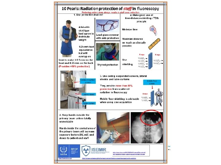
10 Pearls: Radiation protection of staff in fluoroscopy 5. Only 1 -5% of radiation falling on Image receptor Reducing patient dose always results in staff dose reduction the patient’s body exits the other side Stand on the side of the transmitted beam (i. e. by the detector), which contains only 15% of the incident radiation and its respective scatter X ray tube Right! Wrong! Image receptor 6. Keep X ray tube under the patient table and not over it Undercouch systems provide better protection from scattered dose X ray tube Right! Wrong! 7. Use personal dosimetry Use at least two dosimeters One inside the apron at chest level One outside the apron at neck or eye level Additional finger ring dosimeter for procedures requiring hands close to primary beam Real time dosimetry systems are useful X ray tube *Image adapted from ICRP Publication 85 9. Address your concerns about radiation protection to radiation protection specialists (medical physicists) 8. Update your knowledge about radiation protection 10. REMEMBER! Quality control testing of fluoroscopy equipment enables safe and stable performance Know your equipment! Using the equipment’s features appropriately will help reduce doses to patients and staff Use injector devices http: //rpop. iaea. org/RPOP/RPo. P/Content/Documents/ Whitepapers/poster-patient-radiation-protection. pdf http: //rpop. iaea. org http: //www-ns. iaea. org/tech-areas/communication-networks/norp/isemir-web. htm
- Slides: 59