Flue gas Desulphurization A real challenge for Thermal


 is a process to remove SOx from exhaust flue gas using")
 is a group of gas. Among them Sulfur Dioxide (SO 2)")
 are compounds of sulfur and oxygen molecules. Thermal power plants burning")
 can result in breathing problems reduced lung function,")


 Amendment Rules,")

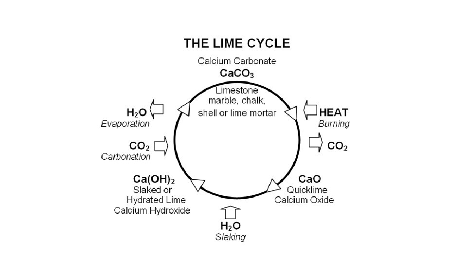
‐ Calcium Gypsum(Ca. SO 4)‐ Calcium Sulfate Carbonate Lime")


2 SO 3 (ammonium sulphite)")


- Slides: 43
“Flue gas Desulphurization” A real challenge for Thermal Power plants by A R Mallick
Insight v. What is Flue gas Desulfurisation? v. Urgency of FGD system Implementation. v. Different Reagents for Desulfurisation. v. Available Techniques for FGD.
Key Focus areas of Thermal Power Plant Heat Rate Auxiliary Power Consumption Plant Load Factor (PLF) Water Consumption Best Practices Safety Availability
New challenge for Thermal Power Plants ‐Flue gas Desulfurisation‐
Flue‐gas desulfurization (FGD) is a process to remove SOx from exhaust flue gas using an alkaline reagent.
Sulfur oxides (SOx) is a group of gas. Among them Sulfur Dioxide (SO 2) is important. Other gases in the group are much less common in the atmosphere. 95% of the SOx emitted from combustion of fossil fuel is sulfur dioxide (SO 2).
Sulfur oxides (SOx) are compounds of sulfur and oxygen molecules. Thermal power plants burning high‐sulfur coal or Oil are generally the main sources of SOX emissions worldwide. Depending on wind, temperature, humidity, and topography, sulfur dioxide can concentrate close to ground level.
High concentrations of sulfur dioxide (SO₂) can result in breathing problems reduced lung function, increased incidence of respiratory symptoms and diseases, irritation of the eyes, nose, and throat, and premature mortality. Sulfur dioxide is the major contributor for acid rain, which acidifies soils, lakes and streams, accelerates corrosion of buildings and monuments, and reduces visibility.
Why it is urgent?
Changes in SO 2 loading over India and China between 2005 and 2016. (By OMI instrument on the Aura satellite(NASA), expressed in Dobson Units (1 DU = 2. 69 × 1016 molecules cm− 2).
v To monitor SO 2 emission, NASA, s Aura satellite captures data by Ozone Monitoring Instrument (OMI). v The data shows India’s SO 2 emission is in raising trend. It has doubled in between 2005 to 2014. v That of china is in decline trend from 2007. China’s first major effort to reduce sulfur dioxide emissions began in 2007 in anticipation of the 2008 Beijing Olympics. Ambitious plan for reduction of emission started at China from 2011. China’s SO 2 emissions have fallen 75% since 2007. v India’s emissions have increased 50% in the same period. v This forces India to implement stringent Emission Norms.
New emission standard for SOx, NOx was notified by the Ministry of Environment, Forests & Climate Change (MOEFCC) in December 2015. MOEFCC had set a deadline of 7 December 2017 for the coal power sector to meet these standards. Most companies have not even started initial work. The industry is asking for some more years to implement these standards. This Stringent norms are also imposed at other countries across the world. Thermal power generation process will become more complex to meet stricter emission norms in future.
Stringent emission norms is set for Thermal power plants in Environment (Protection) Amendment Rules, 2015 to control SOX emission. Units installed before 31 st December, 2003 Units installed after 1 st January, 2003, up to 31 st December, 2016 • 600 mg/Nm 3 (Units Smaller than 500 MW • 200 mg/Nm 3 (for units larger than 500 MW) Units to be installed from 1 st January, 2017 100 mg/Nm 3
Reagent Used By‐Product Limestone(Ca. CO 3)‐ Calcium Gypsum(Ca. SO 4)‐ Calcium Sulfate Carbonate Lime (Ca. O) / Hydrated Lime(Ca(OH)2) Calcium Sulfite (Ca. SO 3) and Sulfate((Ca. SO 4) Ammonia (NH 3) Ammonium Sulfate ((NH 4)2 SO 4 ) Soda Ash (Na 2 CO 3) – Sodium Carbonate / Caustic Soda (Na. OH) – Sodium Hydroxide Sodium Bisulfite (Na. HSO 3) Sea Water None
Selection of the FGD technique depends upon v Type of boiler v Size of the Boiler v SO 2 content in exhaust gases v Emission requirements v Cost and availability of reagents v Utilization and disposal of by‐products
Dry Flue Gas Desulphurization System Available Options Semi‐Dry Flue Gas Desulphurization System Wet Flue Gas Desulphurization System
Dry Flue Gas Desulphurization System Dry injection Process
Semi‐Dry Flue Gas Desulphurization System Spray drying Process Flash Absorption Process
Wet Flue Gas Desulphurization System Limestone scrubbing Process Sodium scrubbing Process Ammonia scrubbing Process Seawater scrubbing Process
Dry Sorbent Injection Process v Sorbent injection system is a low cost method of SOX control. v Calcium and Sodium‐based reagents are used as Sorbent. v Sorbent is stored and injected dry. v This technique is suitable where space availability is limited. v The Sorbent can be injected into furnace and different locations in flue gas path (before and after Air heater). v In furnace sorbent injection, dry sorbent is injected into the upper part of the furnace.
Dry Sorbent Injection
Performance of SOX reduction depends upon • Particle size‐ Finner particles results better performance • Residence time in flue gas • Uniform mixing • Temperature at injection point‐ Higher temperature gives better result, Minimum temperature should be 275 OF. • Injection location.
Chemical Reaction Ca. CO 3 + HEAT → Ca. O + CO 2 Ca. O+SO 2→Ca. SO 3 + ½O 2→ Ca. SO 4 (Gypsum) Sodium carbonate (Soda Ash‐ Na 2 CO 3) can also be used as Sorbent. Na 2 CO 3 + SO 2 → Na 2 SO 3 + CO 2
SO 2 Recovery during Combustion v. In AFBC and CFBC Boilers, controlled Mixing of Sorbent with fuel is done to control SOX v 4% to 8% of lime stone is mixed with coal depending upon purity of lime and sulphur percentage in fuel.
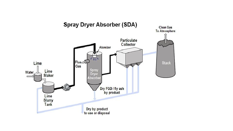
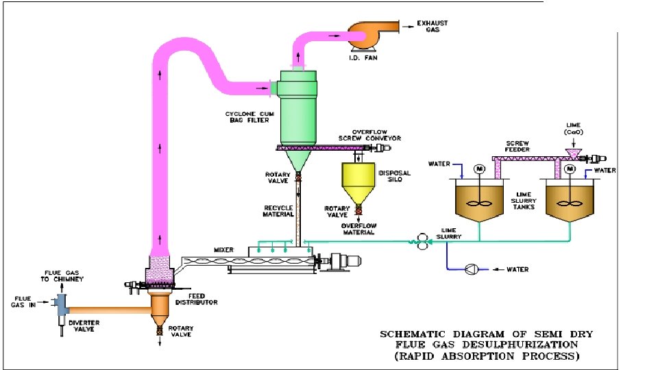
Semi‐Dry System ‐ Spray Drying Process v Lime is used as absorbent in this process. v This process is also known as Lime‐spray drying (LSD) process. Atomized lime slurry is sprayed inside an absorber chamber to the flue gas stream. Water in the spray droplets evaporates. v Lime reacts with SO 2 and form calcium sulfate (Ca. SO 4). v The desulfurized flue gas, along with reaction products passed through a bag filter. Dry solid waste product, i. e‐Ca. SO 3, Ca. SO 4 and unreacted lime is collected at bag filter. v A portion of this solids collected is recycled and mixed with fresh lime slurry to maintain required level of alkalinity in the feed slurry. v The clean gas is discharged to atmosphere through stack.
SO 2 + Ca. O → Ca. SO 3 + ½O 2 → Ca. SO 4 (Gypsum)
Semi‐Dry System ‐ Flash Absorption Process v SO 2 in the flue gas reacts with semi solid mixture of lime. v The reaction by‐product consist of unreacted lime, Ca. CO 3, and Ca. SO 4. v The by‐product collected is recycled along with the fresh lime slurry into the reactor. v No effluent water is generated as the product is collected in dry form.
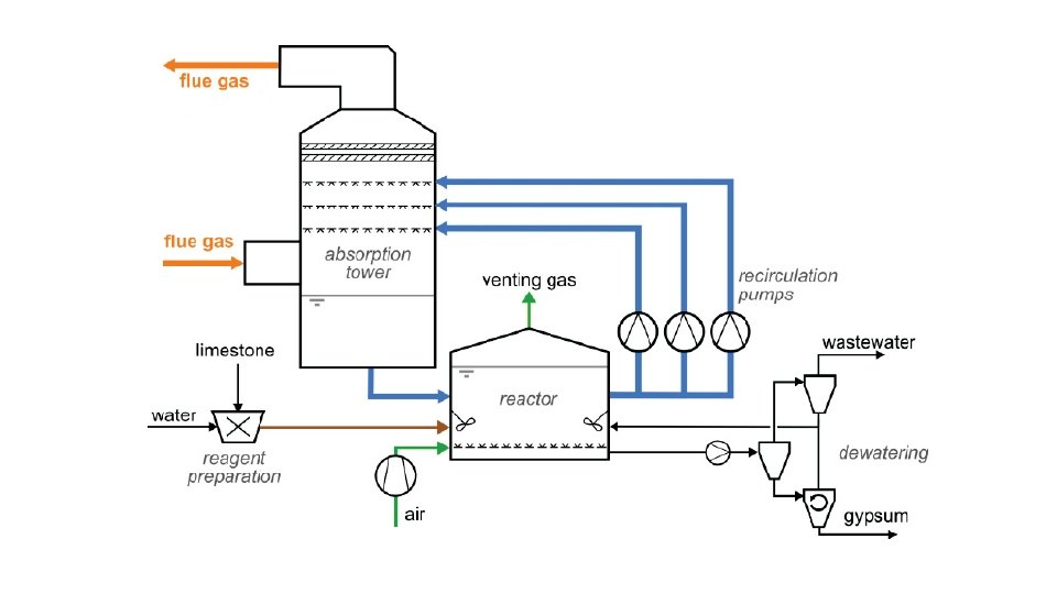
Wet FGD System ‐ Limestone Scrubbing Process v Preferred technology for Flue gas desulphurisation in larger capacity power plants. v System is usually located after electrostatic precipitator or bag‐house. v To get maximum gas–liquid surface area and residence time, various wet scrubber designs like‐ Spray towers, venturis, plate towers, and packed beds are used. v Flue gas normally flows counter currently with respect to the reagent spray. v Slurry of limestone is sprayed on to the incoming flue gas in a scrubber tower. v Sulphur dioxide in the gas reacts with lime and form calcium sulphite
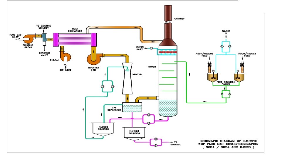
Wet FGD System ‐ Sodium Scrubbing Process v Caustic soda (Sodium Hydroxide, Na. OH, ) or Soda Ash (Na 2 CO 3) is used as scrubbing agent. v SO 2 present in Flue gas is brought in contact with Na. OH / Na 2 CO 3 in a tower. v SO 2 reacts with of Na. OH / Na 2 CO 3 and form Sodium Sulfite (Na 2 SO 3) or Sodium Bisulfite (Na. HSO 3) which is continuously removed from the bottom of the tower.
2 Na. OH +SO 2 → Na 2 SO 3+H 2 O Na 2 SO 3+SO 2 +H 2 O → 2 Na. HSO 3 Na 2 CO 3+2 SO 2 +H 2 O → 2 Na. HSO 3 +CO 2
Wet FGD System ‐ Ammonia Scrubbing Process v Ammonia is used as scrubbing agent. v Does not generate any liquid waste. Ammonium sulfate fertilizer is produced as by‐product. v Ammonia is sprayed through multiple levels of spray nozzles in an absorber. v SO 2 present in flue gas reacts with ammonia, and produces ammonium sulphate (NH 4)2 SO 4. v The by‐product can generate substantial revenue.
2 NH 3+SO 2 H 2 O → (NH 4)2 SO 3 (ammonium sulphite) (NH 4)2 SO 3+ ½ O 2 → (NH 4)2 SO 4 (ammonium sulphate)
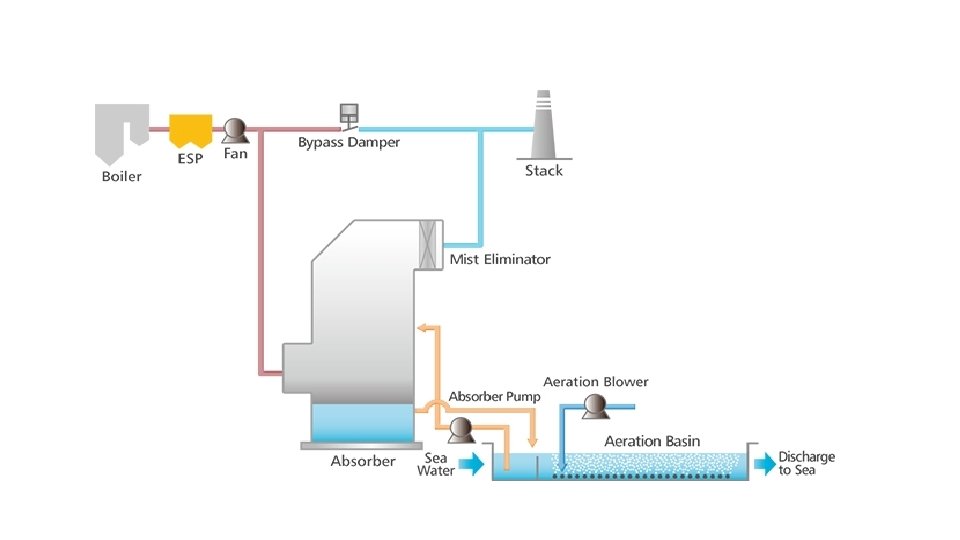
Wet FGD System ‐ Sea Water Scrubbing Process v Can be used at power plants located near sea. v Normal seawater is used as a scrubbing medium by utilizing the alkalinity present in seawater. v Seawater is suitable for absorption of SO 2 for two main reasons: v The hot flue gas flow through the absorber in an upward direction. v The sea water is sprayed over the flue gas. The absorbed SO 2 is transformed into sulfate ions, a natural constituent of seawater. v The reacted seawater flows by gravity to Oxidation chamber, where water is aerated and mixed again with additional sea water. The mixture is then