Flow Measurements 1 Applications Flow Measurement The Bernoulli

Flow Measurements 1

Applications: Flow Measurement The Bernoulli equation can be applied to several commonly occurring situations in which useful relations involving pressures, velocities and elevations may be obtained. A very important application in engineering is : fluid flow measurement Ø Measurement of velocity : Pitot-static tube Ø Measurement of flow rate: 1 -Venturi meter, 2 - Orifice meter & 2 3 - Rotameter

Flow Measuring Devices Pitot Tube • This is an open-ended tube, bent through 90 o with the nose facing the direction of the oncoming flow. • The fluid is brought to rest at the nose so it measures the fluid’s stagnation or total pressure (po). 3

Stagnation Conditions • Fluid on streamline OX forced to zero velocity at X – this is a stagnation point. • The term stagnation is often used to describe the total pressure conditions as this corresponds to when the dynamic pressure term is zero. • The static pressure at zero-velocity conditions thus relates to the total or stagnation pressure. 4

Pitot-Static Tube 1 P 1, V 1 P 2 2 Stagnation Point V 2=0 ØP 1 is a Static pressure: It is measured by a device (static tube) that causes no velocity change to the flow. This is usually accomplished by drilling a small hole normal to a wall along which the fluid is flowing. ØP 2 is a Stagnation pressure: It is the pressure measured by an openended tube facing the flow direction. Such a device is called a Pitot

Pitot-Static tube Bernoulli equation between 1 and 2: v. Stagnation Pressure is higher than Static Pressure (Recall that position 2 is a stagnation point: V 2= 0) We can measure pressures P 1 and P 2 using hydrostatics: P 1=Patm + ρgh 1, P 2=Patm + ρgh 2 or using a Pressure Gauge, see next slide 6

• Or using Bernoulli’s equation for a constant horizontal datum level head: p + ½ ρ V 2 = po – p = ½ ρ V 2 = h ρm g ( 7

Venturi meters, Orifice and Nozzle Basic principle: Increase in velocity causes a decrease in pressure • Fluid is accelerated by forcing it to flow through a constriction, thereby increasing kinetic energy and decreasing pressure energy. • The flow rate is determined by measuring the pressure difference between the meter inlet and a point of reduced pressure. • Desirable characteristics of flow meters: v. Reliable, repeatable calibration v. Introduction of small energy loss into the system v. Inexpensive v. Minimum space requirements 8

v Various flow meters are governed by the Bernoulli and continuity equations. The theoretical flow rate 9

Flow Measuring Devices Venturi Meter: • This device consists of a conical contraction, a short cylindrical throat and a conical expansion. • The fluid is accelerated by being passed through the converging cone. • The velocity at the “throat” is assumed to be constant and an average velocity is used. • The venturi tube is a reliable flow measuring device that causes little pressure drop. It is used widely particularly for large liquid and gas flows. P 1 P 2 Where the discharge coefficient, Cd =f(Re), can be found in Figure shown later 10
")
Flow Measuring Devices Venturi Meter Ignoring friction losses and applying Bernoulli’s equation from (1) to (2). p 1 + ½ ρ V 1 2 = p 2 + ½ ρ V 2 2 Assuming incompressible flow (ρ = constant): p 1 - p 2 = ½ ρ (V 22 - V 12) _______ (eq. 1) Applying continuity equation from (1) to (2): V 2 = (A 1 / A 2) V 1 ______ (eq. 2) 11
 Substituting (eq. 2) into (eq. 1): p")
Flow Measuring Devices Venturi Meter (Cont. ) Substituting (eq. 2) into (eq. 1): p 1 - p 2 = ½ ρ [(A 1/A 2)2 V 12 – V 12] Rearranging: In a nozzle or other constriction, the discharge coefficient (also known as coefficient of discharge) is the ratio of the actual discharge to theoretical discharge, i. e. , the ratio of the mass flow rate at the discharge end of the nozzle to that of an ideal nozzle which expands an identical working fluid from the same initial conditions to the same exit pressures. 12 Discharge coefficient (Cd) typically 0. 97.

13

Flow Measuring Devices Flow Nozzle • Similar to venturi-meter but no diffuser so cheaper and more compact. 14

Orifice Meter The orifice meter consists of an accurately machined and drilled plate concentrically mounted between two flanges. 15

There is a large pressure drop much of which is not recoverable. This can be a severe limitation when considering use of an orifice meter. 16

Flow Measuring Devices Orifice Plate Cd typically 0. 6 - corrects for non-uniformity & jet contraction. 17

18 Orifice plates

Generalized Chart for Cd Cd 19

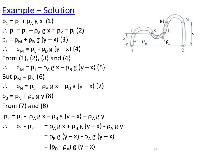
Example : Flow Measurement with an Orifice Plate 1 -Derive an expression for (p 1 – p 2) in terms of ρA, ρB, x and y. 2 -Calculate the pressure difference across the plate, the volume flow rate and average velocity for: pipe diameter = 10 cm, pipe fluid = water (ρA = 1000 kg/m 3), manometer fluid is mercury (SG = 13. 6), orifice plate hole diameter = 5 cm, (y – x) = 30 cm, 20 Cd = 0. 65.
 p 1 - p 2 = (ρB - ρA)")
Example – Solution (Cont. ) p 1 - p 2 = (ρB - ρA) g (y – x) For values given: p 1 - p 2 = 37082 N/m 2 Using: = 0. 0114 m 3/s = 681 L/min Vmean = 0. 0114 / ( x 0. 12 / 4) = 1. 45 m/s 22

Rotameters • Rotameters fall into the category of flow measurement devices called variable area meters. • These devices have nearly constant pressure and depend on changing cross sectional area to indicate flow rate. • Rotameters are extremely simple, robust devices that can measure flow rates of both liquids and gasses. • Fluid flows up through the tapered tube and suspends a ‘float’ in the column of fluid. • The position of the float indicates the flow rate on a marked scale. 23

Rotameters Three types of forces must be accounted for when analyzing rotameter performance: • Flow • Gravity • Buoyancy Gravity For our analysis neglect drag effect Flow 24

Rotameter Mass Balance Assume Gradual Taper Flow Between Float and Tube S 3 is annular flow area at plane 3 25

Rotameter Momentum Balance Note: • p 3 = p 2 • Must account force due to float 26
 27")
Rotameter Mechanical Energy Balance 0 Assume: (Base velocity head on smallest flow area) 27

Rotameter Combining Momentum and Mechanical Energy Balance After Some Manipulation 28

Rotameter Assuming Sf ≈ S a discharge coefficient can be defined CR must be determined experimentally. As Q increases the float rides higher, the assumption that Sf = S is poorer, and the previous expression is more nearly correct. 29

• Example § A Venturi meter with an entrance diameter of 0. 3 m and a throat diameter of 0. 2 m is used to measure the volume of gas flowing through a pipe. The discharge coefficient of the meter is 0. 96. Assuming the specific weight of the gas to be constant at 19. 62 N/m 3, calculate the volume flowing when the pressure difference between the entrance and the throat is measured as 0. 06 m on a water U-tube manometer. • Solution: What we know statement : from the problem rgg = 19. 62 N/m 2 Cd = 0. 96 d 1 = 0. 3 m d 2 = 0. 2 m Calculate Q: V 1 = Q/A 1= Q/0. 0707 V 2 = Q/0. 0314 30
 and (2) :")
For the manometer : For the Venturi meter : Combining (1) and (2) : 31

Flow over notches and weirs • Notch • is an opening in the side of a tank or reservoir, which extends above the surface of the liquid. • It is usually a device for measuring discharge. • A weir is a notch on a larger scale – usually found in rivers. • It may be sharp crested but also may have a substantial width in the direction of flow – it is used as both a flow measuring device and a device to raise water levels. 32

33

Flow over notches and weirs • Weir Assumptions § assume that the velocity of the fluid approaching the weir is small so that kinetic energy can be neglected. § assume that the velocity through any elemental strip depends only on the depth below the free surface. § These are acceptable assumptions for tanks with notches or reservoirs with weirs, but for flows where the velocity approaching the weir is substantial the kinetic energy must be taken into account (e. g. a fast moving river). § The only difference between a notch and a weir is that the notch of a small size and the weir is of a bigger one. § Moreover, a notch is usually made in a plate, whereas a notch is made of masonry or concrete. 34

35

36

• A General Weir Equation • To determine an expression for theoretical flow through a notch we will consider a horizontal strip of width b and depth h below the free surface, as shown in the figure • velocity through the strip • V= • discharge through the strip, • Integrating from the free surface, h = 0, to the weir crest, h = H gives the expression for the total theoretical discharge, • Qtheoritical = 37

• Rectangular Weir • For a rectangular weir the width does not change with depth so there is no relationship between b and depth h. We have the equation, b = constant = B. • Substituting this with the general weir equation gives: • (3. 26) Figure 3. 28 : A rectangular weir To calculate the actual discharge we introduce a coefficient of discharge, Cd, which accounts for losses at the edges of the weir and contractions in the area of flow, giving : (3. 27) 38
- Slides: 38