Flow Leaders and Deflectors Flow Leaders and Deflectors


- Slides: 13

Flow Leaders and Deflectors

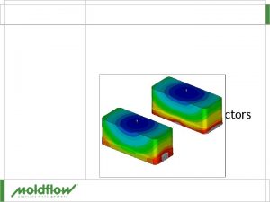
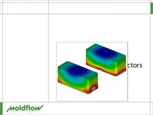
Flow Leaders and Deflectors § Subtle changes in nominal wall thickness – Designed to control the flow front § Flow leaders – Thicker parts of the cavity – Increases the flow front velocity – Yellow arrow § Flow deflectors – Thinner parts of the cavity – Decreased flow front velocity – Red arrow

Why Use Flow Leaders and Deflectors § Balance flows § Move weld lines

Advantages and Disadvantages § Flow Leader – Advantages § Reduce shear stress § After tool is cut flow leader can be added by removing steel – Disadvantages § Add material volume § Possible increase in cycle time § Flow Deflector – Advantage § Reduce material volume – Disadvantage § Possible reduction in structural integrity

Thickness Changes § Leaders/deflectors thickness changes – Should be less than a 25% change from nominal wall § Thickness transition – Should be smooth and gradual – Reality midplane is a step – Fusion & 3 D can model a bevel transition Bad Better Best

Setting the Thickness § Midplane – Easy to change thickness property of selected elements § Fusion – Can set thickness like midplane – Can only use for flow to test flow leader/deflector – Must re-translate with revised thicknesses if going on to cool and warp § 3 D – Test as Fusion model if possible – Otherwise must re-translate

Model Preparation § Use layers to set up flow leader/deflector – Select elements whose thickness is to be changed – Assign them to a new layer – Rename the layer § Possibly align nodes to create a smooth transition

Practice - Window Cover Model § Design Criteria – – Gate location fixed Weld line to be moved to upper right corner of window Move by adding flow deflector Material § Lanxess Lustran ABS 450 C – Molding conditions § Mold temperature 60ºC § Melt temperature 250ºC § Injection time 2. 5 s

Changing Thickness § Select the elements that need to be changed – Flow deflector layer § Assign Properties from the Edit menu – Select an existing property or – Create a new one

Window Cover § Run three analyses – Nominal wall – 1. 9 mm flow deflector – 1. 27 mm flow deflector Nominal Wall § Compare results – – Fill time Weld line Flow front temperature Frozen layer thickness 1. 9 mm th 1. 27 mm th

Window Cover § Flow front temperature – At weld lines – Option for weld line results – Help determines quality

Window Cover § Frozen Layer Fraction in flow deflector – Thinner the wall thickness the higher the frozen layer Nominal Wall 1. 9 mm 1. 27 mm

QUESTIONS
 5 step hard style verbal judo
 Flow lider
 Dfd to structure chart
 Transform flow and transaction flow
 What is rotational flow
 External flow vs internal flow
 Control flow and data flow computers
 Turbulent flow
 Magic box respiratory therapy
 Venturi mask flow rate
 Advantages of venturi mask
 Internal flow vs external flow
 Ecological succession
 Flow of energy vs flow of matter

