FLOTATION INTRODUCTION Objective of Using Flotation Used for

FLOTATION

INTRODUCTION

Objective of Using Flotation • Used for the removal of: - Suspended Solids - Oil and Grease from wastewater the seperation and concentration of sludges

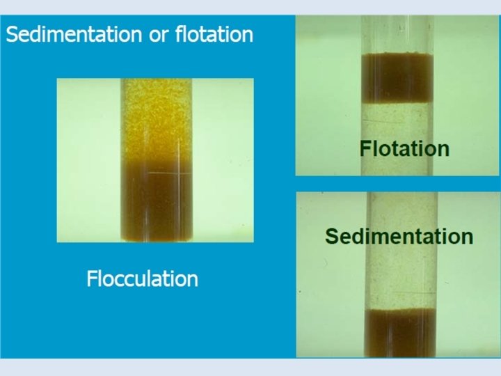
Mechanism of Flotation • If density of particle < density of water can be separated by flotation e. g. ? Petroleum industry Edible oil industry Fiber recycling in paper industry

Flotation Types 1. 2. 3. 4. 5. Simple flotation Flotation with aeration Dissolved air flotation Electroflotation Vacuum flotation
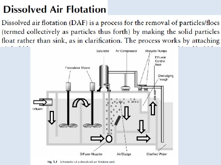

Principal components of flotation system • Pressurized pump elevated pressure to increase solubility • Air-injection facilities • Retention tank (saturation tank) 1 -3 min • Back pressure regulation device constant head on pressurizing pump • Flotation unit circular / rectangular with a skimming device

DAF

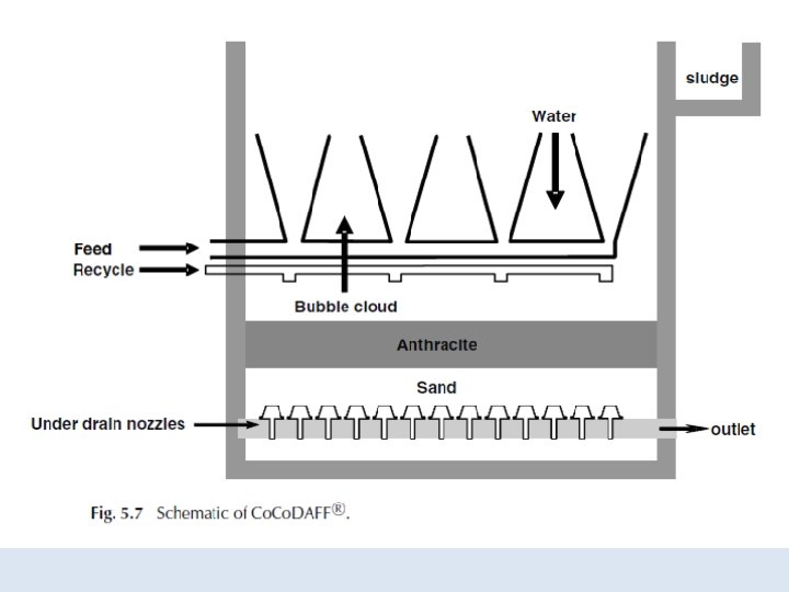
The technology was first pioneered in Sweden in the 1960 s but its use has been reported from many other countries since. A rapid gravity sand or anthracite–sand filter is incorporated in the lower section of the flotation tank such that the effluent from the flotation stage flows directly onto the filter bed. Consequently, the combined unit requires additional depth, up to 2 m, to house the filter bed and underdrain system.
 disturbances in the flow")
The process offers two main advantages over traditional systems: (1) disturbances in the flow which may cause the flocs to break are minimized, and (2) the system can easily be switched to filtration-only operation with the DAF coming on line only when the water becomes excessively polluted.
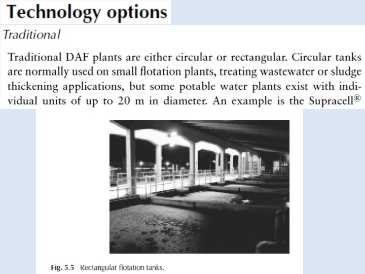
 Traditional DAF plants work in a co-current mode")
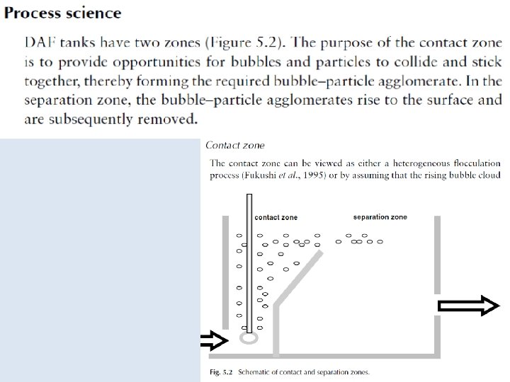
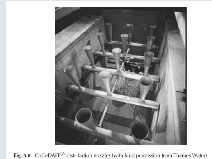
Counter current flotation (Co. DAFF ) Traditional DAF plants work in a co-current mode whereby the bubbles and incoming water are contacted together at the bottom of the tank and then the combined flow travels in a horizontal direction in the separation zone. Co. DAFF operates in a counter current direction with the flow maintained in a vertical direction enhancing both bubble–particle interactions and the time in the contact zone. A key attribute of the system is that the incoming flow is evenly distributed across the flotation tank through a series of submerged laterals and distribution cones.
- Slides: 22