
Flat eBeam and Image Charge Undulator Yine Sun
Flat e--Beam and Image Charge Undulator Yin-e Sun, Philippe Piot, Helen Edwards FNAL Y. Zhang JLab.
Outline • Introduction • Flat beam experiment at A 0: achieved results • Image charge undulator (ICU) • Flat beam and ICU • Required improvement and proposed experiment Yin-e Sun, APC/FNAL 3/8/2021 2
Introduction • High intensity x-rays ← large synchrotron radiation/FEL facilities ← Ge. V electrons beams. • The image charge undulator (ICU) → Me. V electrons beams → high intensity x-rays. – compact and less expensive. – With sub-millimeter gratings, the radiation produced by an ICU can be in the hard x-ray regime for an electron beam energy less than 200 Me. V. • Currently, there is no experimental demonstration of the image charge undulator. • A 0→flat electron beam → Proof-of-principle experiment of the ICU. Yin-e Sun 3/8/2021 3
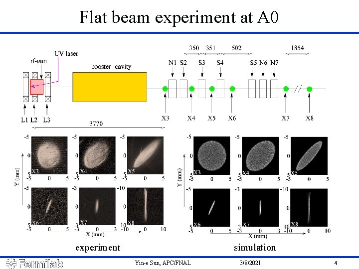
Flat beam experiment at A 0 experiment simulation Yin-e Sun, APC/FNAL 3/8/2021 4
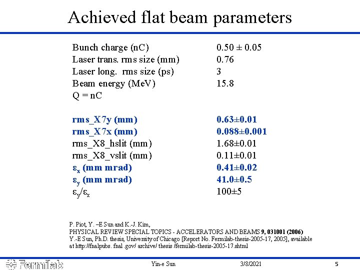
Achieved flat beam parameters Bunch charge (n. C) Laser trans. rms size (mm) Laser long. rms size (ps) Beam energy (Me. V) Q = n. C 0. 50 ± 0. 05 0. 76 3 15. 8 rms_X 7 y (mm) rms_X 7 x (mm) rms_X 8_hslit (mm) rms_X 8_vslit (mm) εx (mm mrad) εy/εx 0. 63± 0. 01 0. 088± 0. 001 1. 68± 0. 01 0. 11± 0. 01 0. 41± 0. 02 41. 0± 0. 5 100± 5 P. Piot, Y. –E Sun and K. -J. Kim, PHYSICAL REVIEW SPECIAL TOPICS - ACCELERATORS AND BEAMS 9, 031001 (2006) Y. -E Sun, Ph. D. thesis, University of Chicago [Report No. Fermilab-thesis-2005 -17, 2005], available at http: //fnalpubs. fnal. gov/ archive/ thesis /fermilab-thesis-2005 -17. shtml Yin-e Sun 3/8/2021 5
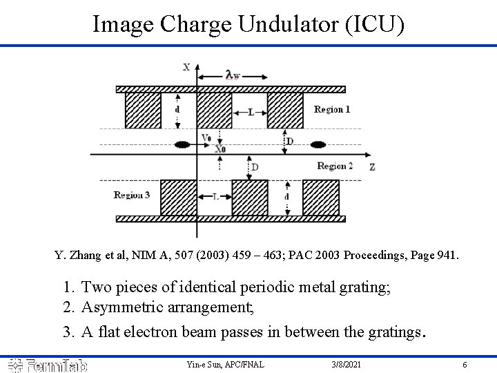
Image Charge Undulator (ICU) Y. Zhang et al, NIM A, 507 (2003) 459 – 463; PAC 2003 Proceedings, Page 941. 1. Two pieces of identical periodic metal grating; 2. Asymmetric arrangement; 3. A flat electron beam passes in between the gratings. Yin-e Sun, APC/FNAL 3/8/2021 6
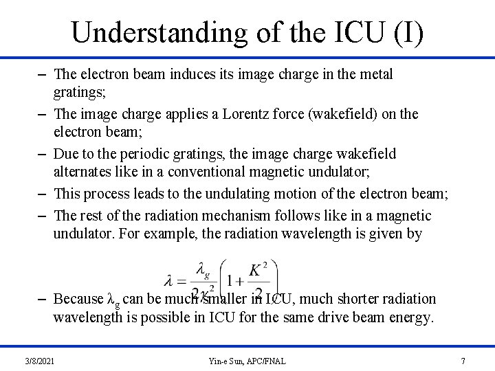
Understanding of the ICU (I) – The electron beam induces its image charge in the metal gratings; – The image charge applies a Lorentz force (wakefield) on the electron beam; – Due to the periodic gratings, the image charge wakefield alternates like in a conventional magnetic undulator; – This process leads to the undulating motion of the electron beam; – The rest of the radiation mechanism follows like in a magnetic undulator. For example, the radiation wavelength is given by – Because λg can be much smaller in ICU, much shorter radiation wavelength is possible in ICU for the same drive beam energy. 3/8/2021 Yin-e Sun, APC/FNAL 7
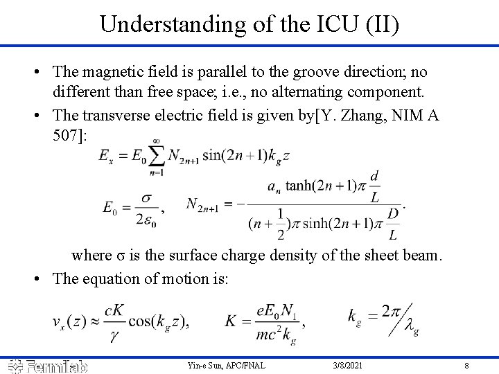
Understanding of the ICU (II) • The magnetic field is parallel to the groove direction; no different than free space; i. e. , no alternating component. • The transverse electric field is given by[Y. Zhang, NIM A 507]: where σ is the surface charge density of the sheet beam. • The equation of motion is: Yin-e Sun, APC/FNAL 3/8/2021 8
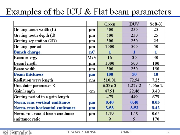
Examples of the ICU & Flat beam parameters Grating tooth width (L) Grating tooth depth (d) Grating separation (2 D) Grating period Bunch charge Beam energy Beam length Beam width Beam thickness Radiation wavelength Undulator parameter K Gain length Grating period in a gain length Norm. rms vertical emittance Norm. rms horizontal emittance Norm. rms round beam emittance ratio μm μm n. C Me. V μm μm μm nm cm μm μm μm Yin-e Sun, APC/FNAL Green 500 500 1000 1 16 1000 500 100 510. 01 6. 33 e-3 47. 91 479 0. 40 3. 53 1. 19 9 DUV 250 250 500 1 30 500 250 50 72. 54 1. 27 e-2 22. 46 449 0. 40 3. 53 1. 19 9 3/8/2021 Soft-X 25 25 25 50 1 30 100 150 10 7. 25 1. 06 e-2 3. 40 679 0. 05 8. 42 0. 65 170 9
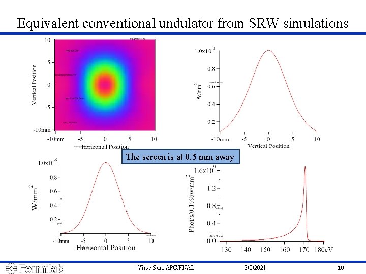
Equivalent conventional undulator from SRW simulations The screen is at 0. 5 mm away Yin-e Sun, APC/FNAL 3/8/2021 10
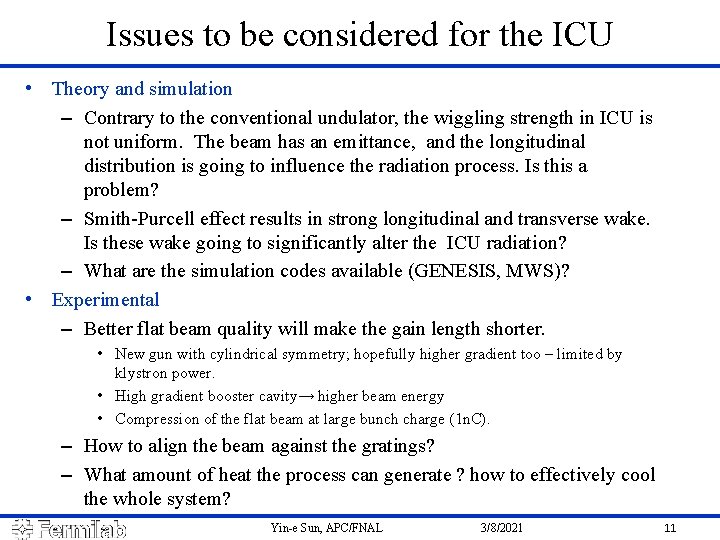
Issues to be considered for the ICU • Theory and simulation – Contrary to the conventional undulator, the wiggling strength in ICU is not uniform. The beam has an emittance, and the longitudinal distribution is going to influence the radiation process. Is this a problem? – Smith-Purcell effect results in strong longitudinal and transverse wake. Is these wake going to significantly alter the ICU radiation? – What are the simulation codes available (GENESIS, MWS)? • Experimental – Better flat beam quality will make the gain length shorter. • New gun with cylindrical symmetry; hopefully higher gradient too – limited by klystron power. • High gradient booster cavity→ higher beam energy • Compression of the flat beam at large bunch charge (1 n. C). – How to align the beam against the gratings? – What amount of heat the process can generate ? how to effectively cool the whole system? Yin-e Sun, APC/FNAL 3/8/2021 11
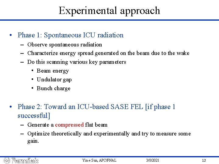
Experimental approach • Phase 1: Spontaneous ICU radiation – Observe spontaneous radiation – Characterize energy spread generated on the beam due to the wake – Do this scanning various key parameters • Beam energy • Undulator gap • Bunch charge • Phase 2: Toward an ICU-based SASE FEL [if phase 1 successful] – Generate a compressed flat beam – Optimize theoretically and experimentally and try to measure some gain. Yin-e Sun, APC/FNAL 3/8/2021 12
Thanks for your attention! Yin-e Sun 3/8/2021 13
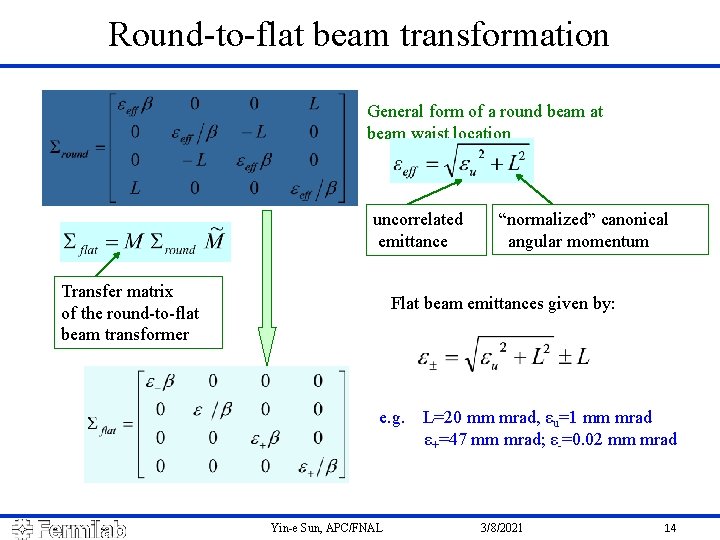
Round-to-flat beam transformation General form of a round beam at beam waist location uncorrelated emittance Transfer matrix of the round-to-flat beam transformer “normalized” canonical angular momentum Flat beam emittances given by: e. g. L=20 mm mrad, εu=1 mm mrad ε+=47 mm mrad; ε-=0. 02 mm mrad Yin-e Sun, APC/FNAL 3/8/2021 14
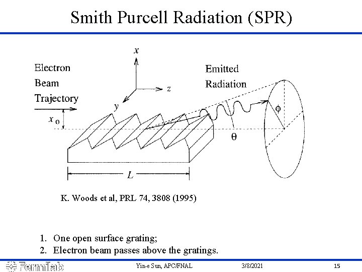
Smith Purcell Radiation (SPR) K. Woods et al, PRL 74, 3808 (1995) 1. One open surface grating; 2. Electron beam passes above the gratings. Yin-e Sun, APC/FNAL 3/8/2021 15
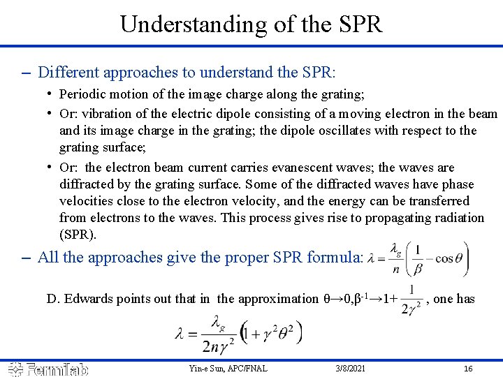
Understanding of the SPR – Different approaches to understand the SPR: • Periodic motion of the image charge along the grating; • Or: vibration of the electric dipole consisting of a moving electron in the beam and its image charge in the grating; the dipole oscillates with respect to the grating surface; • Or: the electron beam current carries evanescent waves; the waves are diffracted by the grating surface. Some of the diffracted waves have phase velocities close to the electron velocity, and the energy can be transferred from electrons to the waves. This process gives rise to propagating radiation (SPR). – All the approaches give the proper SPR formula: D. Edwards points out that in the approximation θ→ 0, β-1→ 1+ , one has Yin-e Sun, APC/FNAL 3/8/2021 16
- Slides: 16