
Finite Elements A Theorylite Intro Jeremy Wendt April





- Slides: 28
Finite Elements A Theory-lite Intro Jeremy Wendt April 2005
Overview • Numerical Integration • Finite Differences • Finite Elements – Terminology – 1 D FEM – 2 D FEM 1 D output – 2 D FEM 2 D output – Dynamic Problem
Numerical Integration • You’ve already seen simple integration schemes: particle dynamics – In that case, you are trying to solve for position given initial data, a set of forces and masses, etc. – Simple Euler rectangle rule – Midpoint Euler trapezoid rule – Runge-Kutta 4 Simpson’s rule
Numerical Integration II • However, those techniques really only work for the simplest of problems • Note that particles were only influenced by a fixed set of forces and not by other particles, etc. • Rigid body dynamics is a step harder, but still quite an easy problem – Calculus shows that you can consider it a particle at it’s center of mass for most calculations
Numerical Integration III • Harder problems (where neighborhood must be considered, etc) require numerical solvers – Harder Problems: Heat Equation, Fluid dynamics, Non-rigid bodies, etc. – Solver types: Finite Difference, Finite Volume, Finite Element, Point based (Lagrangian), Hack (Spring-Mass), Extensive Measurement
Numerical Integration IV • What I won’t go over at all: – How to solve Systems of Equations • Linear Algebra, MATH 191, 192, 221, 222
Finite Differences • This is probably the easiest solution technique • Usually computed on a fixed width grid • Approximate stencils on the grid with simple differences
Finite Differences (Example) • How we can solve Heat Equation on fixed width grid – Derive 2 nd derivative stencil on white board • Boundary Conditions • See Numerical Simulation in Fluid Dynamics: A Practical Introduction – By Griebel, Dornseifer and Neunhoeffer
Finite Elements Terminology • We want to solve the same problem on a non-regular grid • FEM also has some different strengths than Finite Difference • Node • Element
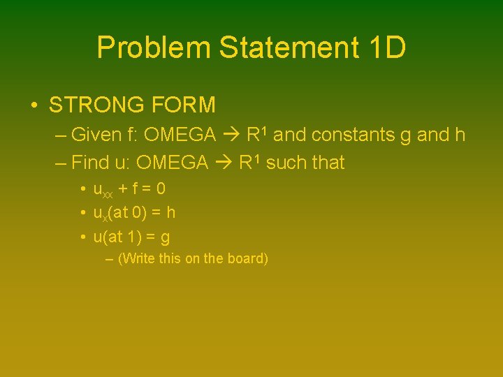
Problem Statement 1 D • STRONG FORM – Given f: OMEGA R 1 and constants g and h – Find u: OMEGA R 1 such that • uxx + f = 0 • ux(at 0) = h • u(at 1) = g – (Write this on the board)
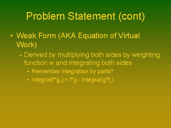
Problem Statement (cont) • Weak Form (AKA Equation of Virtual Work) – Derived by multiplying both sides by weighting function w and integrating both sides • Remember Integration by parts? • Integral(f*gx) = f*g - Integral(g*fx)
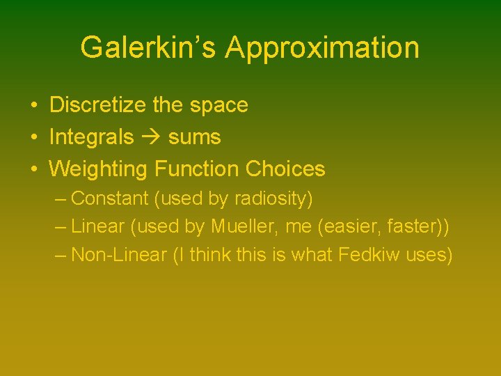
Galerkin’s Approximation • Discretize the space • Integrals sums • Weighting Function Choices – Constant (used by radiosity) – Linear (used by Mueller, me (easier, faster)) – Non-Linear (I think this is what Fedkiw uses)
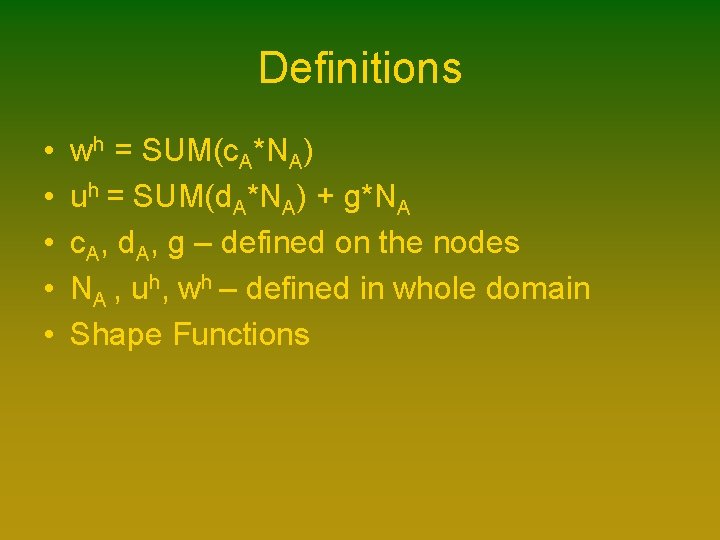
Definitions • • • wh = SUM(c. A*NA) uh = SUM(d. A*NA) + g*NA c. A, d. A, g – defined on the nodes NA , uh, wh – defined in whole domain Shape Functions
Zoom in • We’ve been considering the whole domain, but the key to FEM is the element • Zoom in to “The Element Point of View”
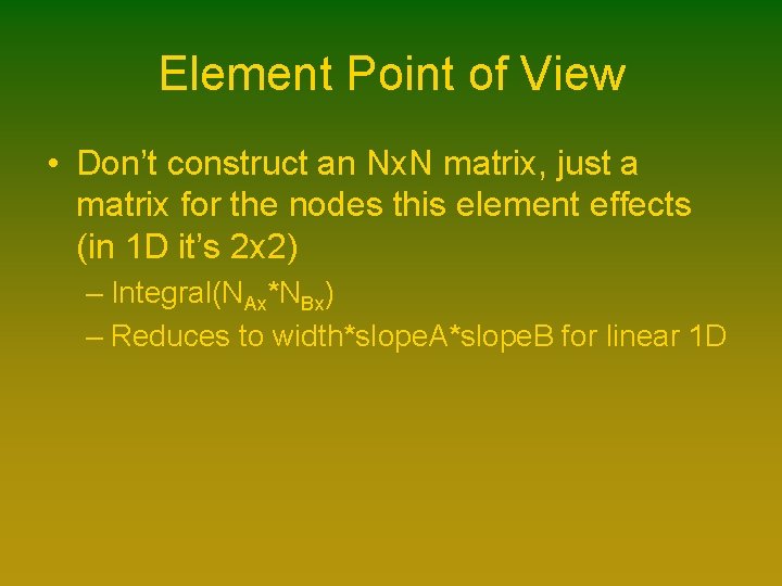
Element Point of View • Don’t construct an Nx. N matrix, just a matrix for the nodes this element effects (in 1 D it’s 2 x 2) – Integral(NAx*NBx) – Reduces to width*slope. A*slope. B for linear 1 D
Now for RHS • We are stuck with an integral over varying data (instead of nice constants from before) • Fortunately, these integrals can be solved by hand once and then input into the solver for all future problems (at least for linear shape functions)
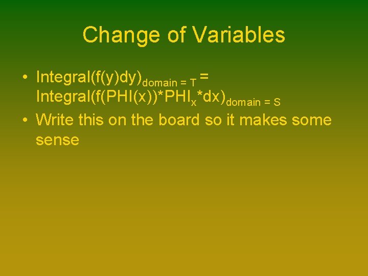
Change of Variables • Integral(f(y)dy)domain = T = Integral(f(PHI(x))*PHIx*dx)domain = S • Write this on the board so it makes some sense
Creating Whole Picture • We have solved these for each element • Individually number each node • Add values from element matrix to corresponding locations in global node matrix
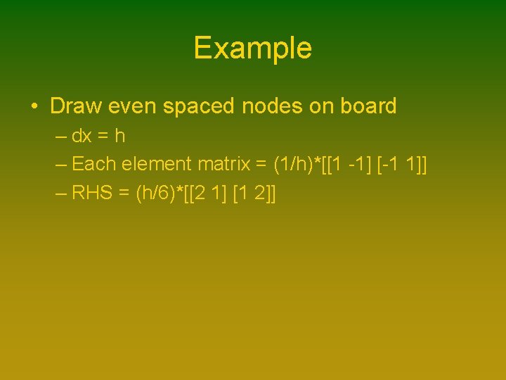
Example • Draw even spaced nodes on board – dx = h – Each element matrix = (1/h)*[[1 -1] [-1 1]] – RHS = (h/6)*[[2 1] [1 2]]
Show Demo • 1 D FEM
2 D FEM 1 D output • Heat equation is an example here • Linear shape functions on triangles Barycentric coordinates • Kappa joins the party – Integral(NAx*Kappa*NBx) – If we assume isotropic material, Kappa = K*I
2 D Per-Element • This now becomes a 3 x 3 matrix on both sides – Anyone terribly interested in knowing what it is/how to get it?
Demo • 2 D FEM - 1 D output
2 D FEM – 2 D Out • Deformation in 2 D requires 2 D output – Need an x and y offset • Doesn’t handle rotation properly • Each element now has a 6 x 6 matrix associated with it • Equation becomes – Integral(BAT*D*BB) for Stiffness Matrix – BA/B – a matrix containing shape function derivatives – D – A matrix specific to deformation • Contains Lame` Parameters based on Young’s Modulus and Poisson’s Ratio (Anyone interested? )
Demo • 2 D Deformation
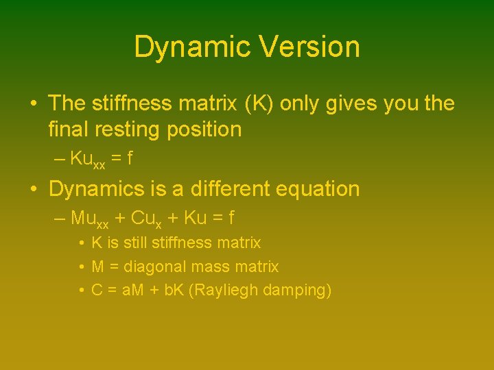
Dynamic Version • The stiffness matrix (K) only gives you the final resting position – Kuxx = f • Dynamics is a different equation – Muxx + Cux + Ku = f • K is still stiffness matrix • M = diagonal mass matrix • C = a. M + b. K (Rayliegh damping)
Demo • 2 D Dynamic Deformation
Questions