FINAL REVIEW Unit 1 ArchitectureCivil Engineering Architecture vs


 Gable Gambrel Hip Gable & Valley Gable with Dormer")


 R-Value: The measurement of thermal resistance used to indicate the")


")


 Footing COLUMN PIER (Concrete or Masonry) SPREAD FOOTING (Concrete) LOAD A footing")
 Foundation A wide strip of reinforced concrete that supports loads from a")


 Weak Soil")
 PILE CAP (CONCRETE) LOAD Pile – Vertical structural member that")
,")


")


- Slides: 90
FINAL REVIEW Unit 1 - Architecture/Civil Engineering • Architecture vs Civil Engineering • Design Element/Principles • Architectural Styles
Definitions Civil Engineering An engineer trained in the design and construction of public works, such as bridges, dams, and other large facilities. Architecture Art and science of designing buildings for human habitation.
Visual Design Elements Six integral components used in the creation of a design: Line Space Color Texture Form and Shape Value
Visual Design Principles Seven principles encompass an interesting design. • Balance • Rhythm • Emphasis • Proportion and scale • Movement • Contrast • Unity
Architectural Styles
Unit 2 - Residential Wood Frame Systems Roof Types Estimating Concrete Heat Loss/Gain Green Building /Sustainable • Energy. Star + LEED • Building Codes • • • Floorplans Foundations Electrical Systems/Plan Plumbing Systems Site considerations Water Supply Storm Water Runoff
Wood Frame Systems
Wall Sections/ Schedules • Wall sections show interior components + materials • Schedules show a list of details about any component within a building. (doors, windows, rooms)
Residential Wall Types Walls are typically constructed from wood, pre -cast concrete, and steel.
Roof Types Shed Low-Slope (Flat) Gable Gambrel Hip Gable & Valley Gable with Dormer Hip & Valley
Common Residential Roofing Materials Standing Metal Seam Clay/Cement Tiles Asphalt Shingles Istockphoto. com® Wood/Cedar Slate
Estimating the Cost of a Pad size = 16 ft x 18 ft floor 4 in. thick • Convert all units to ft 16 ft, 18 ft, . 333 ft • Calculate volume (L x W x t) • Convert ft 3 to yd 3 Concrete is typically sold in increments of ½ yd 3 $98/ yard 3 x 4. 0 yards 3 = $392
Heat Loss and Gain • • • Heat Transfer Winter Heat Loss Summer Heat Gain British Thermal Units (Btu) Formula for Heat Load Heat Loss Through a Wall R-Value Convert R-Value to U-Value Using Engineering Design Data ΔT = Temperature Differential Total Heat Transmission Load
British Thermal Unit (Btu) R-Value: The measurement of thermal resistance used to indicate the effectiveness of insulation. Units: U-Value (coefficient of heat conductivity): The measure of the flow of transmittance through a material given a difference in temperature on either side. Units: Note that R = 1/U
Formula for Heat Load Q' = AU ΔT Where Q' = Total cooling/heating load in A = Area under investigation in ft 2 U = Coefficient of heat conductivity in ΔT = Difference in temperature between outside and inside conditions in °F Click here to return to calculation
Wall R-Value Outside Air Film neglect Siding 1. 05 Insulation 11. 00 Drywall 0. 68 Inside Air Film 0. 68 Total R-Value 13. 41
Convert R-Value to U-Factor Total R-Value= 13. 41 U =. 074 (Do not round up)
ΔT = Temperature Differential The difference between the design outside temperature and the design inside temperature Design Outside Temperature Design Inside Temperature 3 °F 68 °F
Total Heat Loss (or Transmission Load Q' = AU ΔT A = (8 ft) (12 ft) = 96 ft 2 (Area of wall) U =. 074 ΔT = 68 - 3 = 65 °F Click here to see equation
What is Sustainability? Sustainability - Meeting the needs of the present without compromising the ability of future generations to meet their own needs. World Commission on Environment and Development
Sustainable Design Reduces the negative impact on the environment and human health, thus improving the performance during a building’s life cycle. Careful consideration is given to water, energy, building materials, and solid waste.
Principles of Sustainability in Architecture • Economy of Resources - Reduce, recycle, and reuse natural resources • Life Cycle Design - Structured methodology for the building process • Humane Design - Harmony between humans and nature
Sustainable Building Life Cycle • Pre-Building • Post-Building
What is ENERGY STAR? ENERGY STAR is a joint program of the U. S. Environmental Protection Agency and the U. S. Department of Energy with the goal to save consumers money and protect the environment through energy-efficient products and practices.
LEED Defined Leadership in Energy and Environmental Design An independent program developed by the U. S. Green Building Council that provides benchmarks for the design, construction, and operation of high performance green buildings
Building Regulations • Building Codes – Health, safety, and well-being of the public – Protection of human life – Enforced by municipalities(towns, counties, cities, states, etc. ) Zoning Laws – Rules that govern an area • Structure type • Distance of structure from road. • A skyscraper would not be built in a residential home complex
Foundations • Purpose • Considerations • Types of Foundations – Shallow Foundations • • Spread Footings Strip Foundations Slab-on-Grade and Thickened Slabs Mat – Deep Foundations (Commercial) • Piles
Spread (Column) Footing COLUMN PIER (Concrete or Masonry) SPREAD FOOTING (Concrete) LOAD A footing that spreads the load over a broad area which supports one (or a few) load(s) USES Under piers or columns
Continuous (Strip) Foundation A wide strip of reinforced concrete that supports loads from a bearing wall FOUNDATION USES • Under foundation walls • For crawl space/basement WALL (Concrete or Masonry) STRIP FOOTING (Concrete) AD O L
Slab-on-Grade and Thickened Slab WALL Slab-on-Grade – Reinforced concrete floor supported by soil Thickened Slab – A slab on grade with an integral footing created by thickening the slab USES Shallow frost depth or when frost protection is used (instead of strip footing) SLAB-ONGRADE THICKENED SLAB
Mat Foundation A large, heavily reinforced concrete slab placed under the entire building to support loads from several points MAT FOUNDATION USES Heavy loads on weak soil CONCRETE PIER
Deep Foundation LOAD Top Soil PILE CAP PILES Friction Force (Resisting Force) Weak Soil Bearing Force (Resisting Force) Strong Soil The building LOAD is transferred through friction on the sides of the piles and/or bearing on the end of the piles
Pile Foundation PIER (CONCRETE) PILE CAP (CONCRETE) LOAD Pile – Vertical structural member that is driven, jetted, or drilled into the ground in order to gain support from deeper soil layers USES Weak shallow soil with deep satisfactory soils PILE
The Electrical System • • Meter Service panel Building wiring Electrical boxes, receptacles (outlets), and switches – GFCI- Outlet near water sources(kitchen, bathroom, garage) • Lights • Equipment powered by electricity • Other electrical systems – Entertainment (cable, home theater, audio systems, etc. ) – Telecommunications (telephone, security systems, intercoms, etc. )
Electrical Plans Outlet: Switch leg: Represents the wiring between a switch and the electrical component that it controls.
Considerations • • • Solar Orientation Wind Orientation Sound Orientation View Orientation Terrain Orientation Existing Features Site Opportunities Map Landscaping Location of Utilities Building Lines Ingress and Egress Site Plan Requirements • • Initial Details Existing Conditions Proposed Construction Drainage
Water Supply System Network of pipes that transport hot and cold potable water under pressure • Fixture – A device that uses water (sink, toilet, dishwasher, etc. ) • Water Heater – Large insulated tanks that heat cold water to be distributed in the hot water supply lines • Trunk Lines – Hot or cold water pipes that serve many fixtures • Branch Lines – Hot or cold water pipes that serve only one or two fixtures
Water Supply System • Water Main – Supply pipe installed and maintained by a public entity and on public property • Water Service – Pipe from the water main to the building supply pipes • Meter – Measures the amount of water transported through water service • Valve – A fitting used to control water flow (located next to the meter) MAI N E S IC V R E
Drain-Waste-Vent System Network of pipes that transport wastewater and sewer gases from the building • Drain Pipe – A pipe that carries wastewater in a building • Vent Pipe – A vertical pipe that provides circulation of air to and from the drainage system • Trap – A fitting (usually U-shaped) that provides a seal to prevent the flow of sewer gases • Stack – A vertical pipe (waste or vent) that extends through at least one story • Cleanout – An access opening to allow cleanout of the pipe
Drain-Waste-Vent System • Sewage – Any liquid waste containing animal or • • vegetable matter, including liquids containing chemicals Sanitary Sewer – A sewer pipe that carries only sewage Storm Sewer – A sewer pipe that carries storm water or other drainage (but not sewage) Building Sewer or Sewer Lateral – Part of the drainage system from the building to the public, private, or individual sewer disposal system Sewer Main – A sewer pipe installed and maintained by a public entity and on public property L LATERA MA IN
HVAC Plans-Plumbing, Vents, AC Image Courtesy Novus Architects
Water Supply System
Sample problems
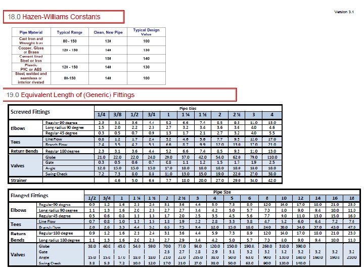
Calculating Head Loss Example What is the head loss in the 10 inch cast iron supply line with a flow rate of 110 gpm if the pipe is 3. 2 miles long and includes the fittings from the previous slide?
Calculating Head Loss Hazen-Williams Formula
Development and Storm Water Runoff 40% evaporation 38% evaporation 20% runoff 10% runoff 25% shallow infiltration 25% deep infiltration Natural Groundcover 21% deep infiltration 10 - 20% Cover 30% evaporation 35% evaporation 55% runoff 30% runoff 20% shallow infiltration 21% shallow infiltration 15% deep infiltration 35 – 50 %l Cover 10% shallow infiltration 5% deep infiltration 75 - 100% Cover
Storm Water Formulas Process • Calculate Pre-Development • Calculate Post-Development • Subtract Pre from Post for change in runoff
Sample
Unit 3 - Commercial • • Framing Systems Wall Systems Floor Systems Roof Systems Structural Design Loads/Load Paths Beam Analysis Spread Footing • • Surveying Parking Lot Design Landscape Soil Testing Low Impact Development Storm Water Storage Legal Descriptions
Commercial Structural Framing Systems • Purpose • Low Rise Framing Systems • Cast-in-Place Concrete • Structural Steel • Load Bearing Walls • Hybrid Systems • Cost • Structural Efficiency
PURPOSE • The purpose of structural framing is provide • Strength – Holds the structure up (and holds it down) despite • Gravity (vertical) loads • Lateral (sideways) loads • Stability – Maintains the shape and minimizes movement
Commercial Wall Systems • Load Bearing Walls – Low Rise – Cast-in-Place Concrete – Tilt-up Concrete – Concrete Masonry Units • Non-Load Bearing Walls – Curtain Walls
Comercial Wall Systems • Load Bearing Wall – Supports vertical loads other than its own weight – Often supports floors or roof above • Non-Load Bearing – Supports only it own weight – Typically used as • Partition walls to separate interior spaces • Protection from the elements
Commercial Roof Shapes Roofs for small commercial buildings can be similar to residential pitched roof shapes. Shed Gable Hip Gable with Dormer Low-slope Gambrel Gable & Valley Hip & Valley Low-slope roofs (not completely flat) are common in large commercial construction.
Commercial Floor Systems • Ground Floor – Slab-on-Grade • Elevated Floor – Precast Concrete – Cast-in-Place Concrete • Concrete Floor Design – Load-Span Tables
Commercial Floor Systems In low rise commercial buildings, floor systems may resemble residential framing using wood or light -gauge steel. In many larger commercial buildings, floors are constructed with reinforced concrete. Courtesy Carolina Concrete Masonry Association
Structure of a Building The primary function of a building structure is to support and transmit the building loads and forces to the ground. Photos courtesy Tilt-up Concrete Association Characteristics: Strength, Stability, Economic Value
Loads and Load Paths • Structural Design • Design Loads – – • • Dead Load Live Load Snow Load Lateral Loads Load Types Load Combinations Load Path Calculating Beam Loads
Calculating Beam Loading Assume that the floor system must support its own weight of 40 psf (dead load) and a live load of 100 psf. What is the uniform load applied to the beam? Total Floor Load = 40 + 100 = 140 psf Uniform Load = Floor Load ∙ Tributary Width
Calculating Column Loads Assume that the floor system must support its own weight of 40 psf (dead load) and a live load of 100 psf. What is the column load for column B 3? Total Floor Load = 40 + 100 = 140 psf Column Load = Tributary Area ∙ Total Floor Load
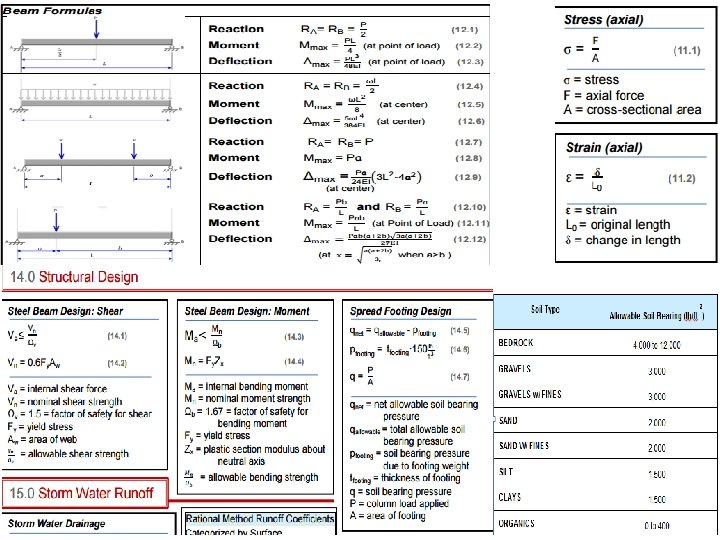
Beam Analysis • Example : simple beam with a uniform load, w 1= 1090 lb/ft • Span = 18 feet
Shear and Moment Diagrams Shear Moment Max. Moment = 44, 145 l ft-lb Max. Shear = 9, 810 lb
Axial Stress Example: Find the tensile stress of a 2 in. x 3 in. tension member subjected to a 45 kip axial load. 1 kip= 1000 lbs
Strain Example: Calculate the strain if a 16 ft long structural member elongates 1. 5 in. when subjected to a tensile load of 67 kips.
Stress and Strain • Elastic behavior – material will return to its original shape when unloaded • Plastic behavior – material will retain some deformation when unloaded • Structural members are designed to act elastically during the service life of a building Yield Point
Beam Design Example Choose the lightest wide flange steel section available to support a live load of 790 plf and a dead load of 300 plf over a simple span of 18 feet. Assume the beam will support a plaster ceiling. Use Fy = 50 ksi.
Beam Design Example Max Shear Max Bending Moment
Bending Strength Select beam based on bending. where = 1. 67
Bending Strength Since W 10 x 17 works Z x = 18. 7 in. 3 > 17. 7 in. 3 But a W 12 x 16 weighs less with Z x = 20. 1 in. 3 > 17. 7 in. 3
Shear Strength Check shear strength. where
Shear Strength Since For a W 12 x 16 d = 11. 99 in. t w =0. 220 in. 79, 134 lb ≥ 14, 715 lb W 12 x 16 works and
Sizing a Spread Footing Size based on: • The total load applied to the soil • The allowable soil bearing capacity The pressure applied due to the total load must be less than or equal to the allowable bearing capacity LOAD SOIL BEARING PRESSURE
Required Footing Area Using Net Allowable Soil Bearing Pressure Where q = Soil bearing pressure P = Load applied A = Area of the footing
Process Step 1 Step 2 1 ft 2 Step 3 t footing A= area of the footing Concrete has a density of 150 lb/ ft 3
Calculate the Net Allowable Soil Bearing Pressure
Required Footing Area
Footing Shape
6’ -6” Square Footing Size 6’ -6” Use 6'- 6'' x 1'- 9'' thick
Round Footing Size 7' '' -6 Say 3 ft 9 in. radius Use 7'- 6'' diameter x 1'- 9'' thick
Differential vs Loop Surveying • Differential • Instrument is setup once • First reading is taking from a benchmark to establish height of instrument. – HI=Benchmark elevation + rod reading(Backsight or BS) – HI=Height of instrument – BS=Measuring to a point with a known elevation • All other points are measured (Forsight: FS) – FS -Measuring a point with a unknown elevation • Only one Backsight is needed since instrument stays in one location – HI= Elev + BS – Elev=HI-FS
Differential vs Loop Surveying • Loop • Instrument is setup more than once therefore a BS and FS are taken each time instrument is setup. – This method is used when obstructions are in the line of sight of the instrument so multiply readings are taken until the point to be measured is reached • Process: BS+ ELEV= HI, HI-FS=ELEV, Repeat
Closure Error/Estimated Distance Closure Error=Final Elev. - Initial Elev. Estimated Distance= (Top Stadia-Bottom Stadia) *100
Parking Lots + Landscape
Soil
Low Impact Development
Detention/Retention Ponds
Legal Descriptions
START