Filtration and Coil Fouling Jeffrey Siegel and Michael


 8 °C (46 °F) Courtesy Jim")
 18 °C (64 °F) Courtesy Jim Westberg")


 Siegel and")


")


- Slides: 21
Filtration and Coil Fouling Jeffrey Siegel and Michael Waring The University of Texas at Austin
Motivation • What is role of filters in protecting coils? • My intent – Predict fouling • Accidental results – Filter sales collateral
Courtesy Paul Francisco
Why do we care? 22 °C (71 °F) 8 °C (46 °F) Courtesy Jim Westberg
Reduced Heat Transfer 27 °C (81 °F) 18 °C (64 °F) Courtesy Jim Westberg
Coil Dust
Major Coil Fouling Effects • Negative – pressure drop increases, fan energy increases • Negative – heat transfer decreases system energy increases • Positive – surface area increases, system energy decreases
Two Perspectives 1. Heat transfer reduction by insulation doesn’t matter that much • • It is all about fan energy Good thing – relatively easy to calculate But, fan pressure drop and filter pressure drop have similar effect Therefore, coil fouling doesn’t matter from an energy perspective.
Two Perspectives 2. It is all about insulation on the coil • • Fan energy is very small component Bad thing – difficult to calculate Highly dependent on particle composition and deposition location Also, competition between small positive and large negative impact
Previous Studies On Coil Fouling • • Krafthefter et al. (1986, 1987) Siegel and Nazaroff (2002, 2003) Groll et al. (2004) Others (Proctor, Braun, etc. ) • Why don’t we know the answers yet? • Use of test dust for experiments • Very limited field data • Insufficient range of testing and simulations
Ongoing Research • Simulate coil fouling in commercial systems • Need to consider several factors • • • Sources of particles Air systems operation Coil condition Filtration Losses in ducts
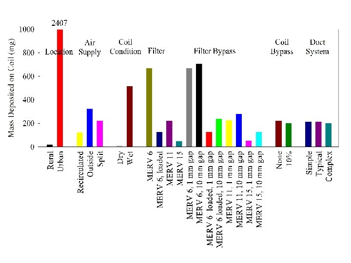
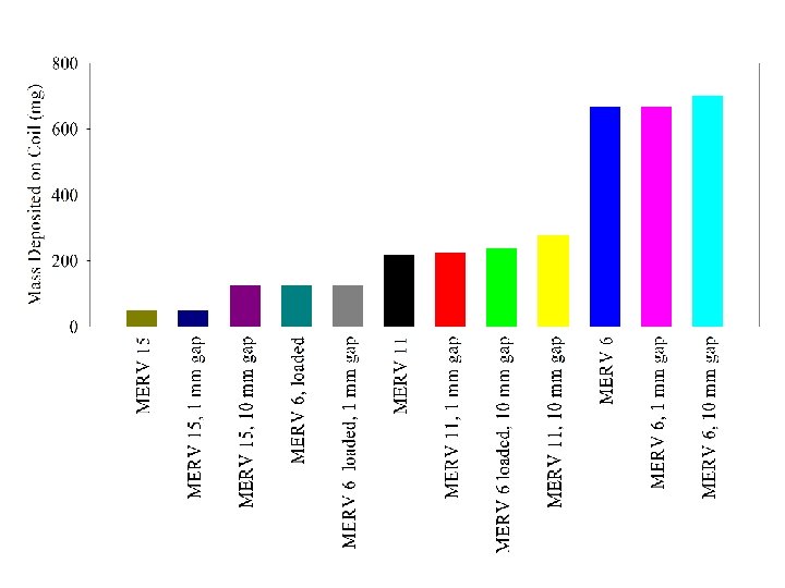
Simulation Parameters • Basic • • 12 FPI coil 2 m/s face velocity 10000 CFM 1 month of continuous operation • Assumptions • No indoor sources • Typical values for other parameters • Varying • Urban vs. rural location • 100% outside air, 100% recirculating, split • Wet, dry coil • MERV 6 (clean and dust loaded), MERV 11, MERV 15 • No bypass, 1 mm, 10 mm • Simple, typical, complex, duct system
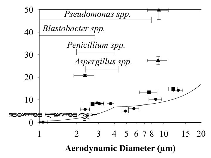
What Size Particles are Responsible?
MERV 6 0. 01 - 0. 1 µm 0. 1 - 1 µm 1 - 5 µm 5 - 10 µm 10 - 100 µm MERV 6 Dust Loaded 0. 01 - 0. 1 µm 0. 1 - 1 µm 1 - 5 µm 5 - 10 µm 10 - 100 µm MERV 11 MERV 15 0. 01 - 0. 1 µm 0. 1 - 1 µm 1 - 5 µm 5 - 10 µm 10 - 100 µm
MERV 6 0. 01 - 0. 1 µm 0. 1 - 1 µm 1 - 5 µm 5 - 10 µm 10 - 100 µm MERV 6, with 1 cm bypass 0. 01 - 0. 1 µm 0. 1 - 1 µm 1 - 5 µm 5 - 10 µm 10 - 100 µm MERV 15, with 1 cm bypass 0. 01 - 0. 1 µm 0. 1 - 1 µm 1 - 5 µm 5 - 10 µm 10 - 100 µm
Summary • Filters work to protect coils • But, we have limited (and conflicting) information on energy and system consequences
Biological Fouling Courtesy Richard Corsi
Strategies • Protect coils with appropriate filtration • Avoid claiming energy savings • Appropriate to speculate about biological fouling • Support research in this area