File and Database Design Objectives Define the terms

File and Database Design Objectives • Define the terms entity, file, record, and attribute and discuss the various types of keys • Draw an entity-relationship diagram, and explain the types of entity relationships • Define cardinality, cardinality notation, and crow’s foot notation • Explain normalization, including examples of first, second, and third normal form 1

File Concepts This chapter devoted to the design of files and databases for information systems. We begin this chapter with a review of file terminology and concepts. Then, we examine the different types of system files. Alter discussing file access methods, we review the various media used for system files and databases. Finally, we examine each type of file organization, and then discuss the advantages and disadvantages of each. 2

Terminology and concepts In your previous programming courses, you probably created and accessed many files, so you are already familiar with most, if not all, of the terminology and concepts that relate to files. This and the next chapter are based on a basic understanding of system files, so let’s take time first to review file terminology and concepts. 3

• File components The smallest amount of data that can be stored is the bit. Bits are grouped into bytes (or characters). Collections of bytes form a field. A field is an individual element of data or a fact about a person, place, thing, or event. A field is also called a data element or a data item. A file is a collection of logical records and contains data about an information system entity. An entity is a person, place, thing, or event for which data is collected. For example, PRODUCT is an entity in an inventory system. 4

ORGANIZING DATA IN A TRADITIONAL FILE ENVIRONMENT Data Hierarchy in a Computer System 5

file A file consists of blocks, which consist of logical records, which consist of related fields. 6

• Entity: Person, place, thing, event about which information is maintained • Attribute: Description of a particular entity • Key field: Identifier field used to retrieve, update, sort a record 7

Entitities and Attributes 8

• Types of files An IS uses one or more of each of the following types of files: • Master files • Table files • Transaction files • Work files • Security files • History files • Key fields • Primary keys A primary key is the field or combination of fields in a master file or table file 9

that minimally and uniquely identifies a particular entity. • Candidate keys Sometimes you do have a choice of two or more fields or field combinations for the primary key. Any field that could serve as the primary key is called a candidate key. Only one of the candidate keys is designated as the primary key; typically, you select the field that is smallest and easiest with which to work. • Foreign keys A foreign key is a field or combination of fields in a file that must match a 10

primary key value in some other file, thereby establishing a relationship between the two files. Foreign keys are found in all types of files. • Secondary keys • Data storage Data can be stored in five basic data storage formats: EBCDIC, ASCII, packed decimal, binary, and floating point. Floating point, which is an inexact representation of a numeric value, is used primarily in scientific applications. Business systems analysts are most concerned with the other four. 11

12

Primary Key 13

Foreign Key 14

Foreign Key 15
 the")
Access methods File access concerns how the system’s programs access (read or write) the file records: sequentially or randomly. File media summary The media usually used for system files are magnetic tape, magnetic disks and diskettes, mass storage devices, and optical disks. File organization The three file organization techniques available are sequential, direct, and indexed. 16

Problems with the Traditional File Environment • • • Data redundancy Program-Data dependence Lack of flexibility Poor security Lack of data-sharing and availability 17

File and Database design Many of your file and database design efforts are actually completed during the systems analysis phase. During systems analysis, you identify and describe all the data elements in the information system, create data flow diagrams, designate data stores, assign the data elements to those data stores, and normalize the data store designs. During the systems design phase, you evaluate and refine your data store designs. 18

Entity-relationship diagrams We have previously defined an entity as a person, place, thing, or event for which data is collected. A relationship is a logical association between entities. A relationship exists between the entities PRODUCT and WAREHOUSE, for example, because products are stored in warehouses. The logical relationships between entities in an IS are graphically represented in an entityrelationship diagram (ERD). The basic format of an ERD for two related entities. 19

20

ENTITY 1 Example DOCTOR IS RELATED TO ENTITY 2 A patient is treated by a doctor TREATS A doctor treats a patient PATIENT 21

Entities. . . ENTITY NAME - entity id - attribute 1 - attribute 2 - …………. . - attribute n CUSTOMER - Customer_ID - Cust_Name - Cust_Address - Cust_Phone 22

Cardinality specifies how many instances of an entity relate to one instance of another entity. Ordinality is also closely linked to cardinality. While cardinality specifies the occurances of a relationship, ordinality describes the relationship as either mandatory or optional. In other words, cardinality specifies the maximum number of relationships and ordinality specifies the absolute minimum number of relationships. When the minimum number is zero, the relationship is usually called optional and when the minimum number is one or more, the relationship is usually called mandatory. 23

24

25

26

27

Three types of relationships can exist between entities. A one-to-one relationship, abbreviated as 1: 1, exists when there is exactly one of the second entity for each of the first entity. Examples One office manager heads one office One vehicle ID number is assigned to one vehicle One driver drives one delivery truck OFFICE MANAGER 1 HEADS 1 BRANCH OFFICE 28

A one-to-many relationship, abbreviated as 1: M Examples One individual owns many automobiles One customer places many orders One department employs many employees One faculty advisor advises many students DEPARTMENT 1 EMPLOYS M EMPLOYEE 29

One-to-One Relationships 30

One-to-Many Relationships 31

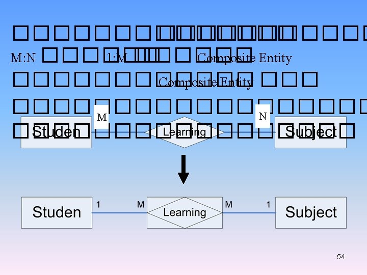
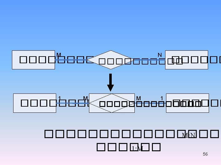
A many-to-many relationship, abbreviated as M: N Examples A student enrolls in one or more classes, and each class has one or more students registered A passenger buys tickets for one or more flights, and each flight has one or more passengers An order lists one or more products, and each product is listed on one or more orders 32

ORDER M LISTS N PRODUCT CUSTOMER M BOUGHT N PRODUCT STUDENT M TAKES N COURSES ORDER M LIST N PRODUCT 33

Many-to-Many Relationships 34

CUSTOMER 1: 1 PLACES 0: M ORDER 0: M CONTAINS 1: M Ordinality and Cardinality PRODUCT 35

36

Normalization The normalization process involves three types of normal forms; first normal form, second normal form, and third normal form. STUDENT Unnormalized STUDENT records 37

First normal form • STUDENT 1 NF STUDENT records This STUDENT record design can be written as: STUDENT (STUDENT-NUMBER, STUDENT-NAME, TOTAL-CREDIT, GPA, ADVISOR-NUMBER, ADVISOR-NAME, COURSE-NUMBER, COURSE-DECS, GRADE) 38

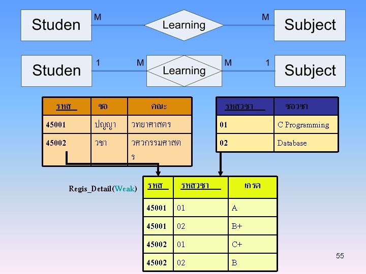
• Second normal form STUDENT primary key base on combination of two fields 2 NF STUDENT, COURSE, and GRADE records 39

• Third normal form 3 NF STUDENT, ADVISOR, COURSE, and GRADE records 40

Our final 3 NF design for all the entity records is: STUDENT (STUDENT-NUMBER, STUDENT-NAME, TOTAL-CREDIT, GPA, ADVISOR-NUMBER) ADVISOR (ADVISOR-NUMBER, ADVISOR-NAME) COURSE (COURSE-NUMBER, COURSE-DECS, NUM-CREDIT) GRADE (STUDENT-NUMBER, COURSE-NUMBER, GRADE) 41

Normalization Repeating groups In the ORDER table design, records 1 and 2 have repeating groups because they contain several products. ORDER-NUM is the primary key for the ORDER table, and PRODUCT-NUM serves as a primary key for the repeating group. Because it contains a repeating group, the ORDER table design is unnormalized. [1] 42
![Normalization [1] The ORDER table as it appears in 1 NF. The repeating groups](http://slidetodoc.com/presentation_image/da809da555d04339eadaa29f5dfb74c1/image-43.jpg "Normalization [1] The ORDER table as it appears in 1 NF. The repeating groups")
Normalization [1] The ORDER table as it appears in 1 NF. The repeating groups have been eliminated. Notice that the repeating group for order 40311 has become three separate records, and the repeating group for order 40312 has become two separate records. The 1 NF primary key is a combination of ORDER-NUM and PRODUCT-NUM, which uniquely identifies each record. 43
 • Steps in building ERDs • Identify the entities")
Building an Entity-Relationship Diagram (ERD) • Steps in building ERDs • Identify the entities • Add attributes • Identify relationship Identify the entities • Identify major categories of information • Check the DFD for data stores, external entities, and data flows • Verify that there is more than one instance of the entities. 44

Add attributes • Identify attributes of the entity that are relevant to the system under development • Check the DFD for details on data stores, and data flows • Check the data requirements of the user requirements • Interview knowledgeable users • Perform document analysis on existing forms and reports 45

Identify relationships • Start with an entity and identify all entities with which it shares relationships • Describe the relationship with the appropriate verb phrase • Determine the cardinality by discussing the business rules with knowledgeable users ERD Building Tips • Data stores of the DFD should correspond to entities • Only include entities with more that one instance of information 46

SALES 1 SERVES M CUSTOMER 1 PLACES M ORDER M LISTS M WAREHOUSE STORES N N PRODUCT 47

ADVISOR 1 ADVISES M STUDENT 1 RECEIVES COURSE 1 GIVES M M GRADE The ERD for STUDENT, ADVISOR, COURSE, and GRADE after normalization 48

name category name stockprice Product buys address makes Company Person employs name ssn 49

50

An Unnormalized Relation of ORDER Figure 7 -11 51

An Normalized Relation of ORDER Figure 7 -12 52

Relational Databases Notice that the relational design avoids redundancy and that all tables are in 3 NF (all nonkey fields are functionally dependent on the primary key, the whole key, and nothing but the key). 53

Database In a typical file processing environment, each end user department has its own information system, and each information system has its own collection of files. Two potential problems might occur with this environment. First, data redundancy, in which data common to two or more information systems is duplicated in multiple files, is possible. Data redundancy obviously results in using extra storage space. The second problem with the typical file processing environment concerns management decision support. A top-level manager might need to relate 58

information from more than one end user department; this requires accessing independent information systems, which might be an awkward and inefficient process at best. Database technology presents a solution to these problems. We define a database as a structure that can store data relating to multiple entities, as well as relationships among those entities. • Database management systems A database management system (DBMS) is a software system used to create, access, and control the database. The DBMS serves as a bridge, or interface, 59

Payroll system Project Control system General Ledger system Database Management system Personnel system Budget Analysis system Database The database environment in which multiple information system access a single, integrated database. 60

between the database and the application programs, systems analysts, and end users of the database. A DBMS includes a data definition language, a data manipulation language, a query language, a data dictionary, and utility services. • Data definition language A data definition language (DDL) is used to describe the structure of the database. The complete definition of the database, which includes descriptions of all fields, records, and relationships, is called the schema. You also use the DDL to define or more subschema for the database. A subschema is a view of the database 61

used by one or more programs or end users. A subschema defines only those portions of the database that a particular program or end user needs or is allowed to access. • Data manipulation language A data manipulation language (DML) provides the commands necessary for storing, retrieving, updating, and deleting database records. DML commands can be embedded in applications programs written in host languages, which are procedural programming languages such as COBOL, BASIC, and PL/1. 62

• Query language A query language is a nonprocedural language used to access a database. • QBE (Query-By-Example) • SQL (Structured Query Language) • Data dictionary The data dictionary in a DBMS is the central storehouse of information about the database. The schema and all subschemas are stored in the data dictionary. 63

• Database models The four basic models for database organization are hierarchical, network, relational, and object-oriented. The hierarchical model is the oldest of these models. Next came the network model and then the relational model. The object-oriented model is the newest of the four. All new DBMS over the past few years have been either relational or object-oriented DBMS. • Relational database In a relational database, data is organized in two-dimensional tables called relations. Each row in a table is called a tuple and each column is called an 64

attribute. You can think of a relation or table as a file, tuples or rows as records, and attributes or columns as fields. Examples of relational database programs: –Microsoft Access ® –Microsoft SQL Server™ –Oracle –DB 2 –Fox. Pro 65

• Object-oriented databases In the last several years, a new approach to the system development process has emerged: the objectoriented approach. In answer to this new approach to system development, object-oriented DBMSs are now available. Man of these current DBMSs are actually hybrids that combine object-oriented features within the framework of the relational model. 66

PERSON OBJECT Number: ID number Name: Name DEPARTMENT OBJECT Deptnum: Department number Deptname: Department name FACULTY: FACULTY OBJECT; MV (all the faculty members within a given department) MAJOR: MAJOR OBJECT; MV (all the majors for a given department) FACULTY OBJECT PERSON: PERSON OBJECT STUDENT: STUDENT OBJECT; MV (all advisees of a given faculty member) DEPARTMENT: DEPARTMENT OBJECT; SUBJECT [Deptnum] (the department to which the faculty member belongs) STUDENT OBJECT PERSON: PERSON OBJECT Totcred: Total credits GPA: GPA MAJOR: MAJOR OBJECT; SUBSET [Majcode] (the student’s major) FACULTY: FACULTY OBJECT; SUBSET [Number, Name] (the name and number of the student’s faculty advisor) MAJOR OBJECT Majcode: Major code Majdesc: Major description STUDENT: STUDENT OBJECT; MV (all students with a given major) DEPARTMENT: DEPARTMENT; SUBSET [Deptnum] (the department to which the major belong) 67

Advantages of the database approach 1. Economy of scale. 2. Sharing of data 3. Balancing conflicting requirement 4. Enforcement of standards 5. Controlled redundancy 6. Security 7. Increased programmer productivity 8. Data independence 68

Disadvantages of the database approach 1. Size. 2. Complexity. 3. Cost. 4. Additional hardware requirements 5. Higher impact of a failure 6. Performance compromises 69

Designing files and database The following four analysis and design steps constitute a systematic method for the creation of file and database designs. To illustrate the steps, we will use as an example a microcomputer information system for an independent video rental store. 1. Create the initial ERD. Identify all the data stores in your DFD as system entities, and create a rough draft of a complete ERD for the system. MEMBER M RENTS N VIDEO 70

MEMBER (MEMBER-NUMBER, NAME, ADDRESS, CITY, STATE, ZIP, HOME-PHONE, WORK-PHONE, CREDIT-CARD-CODE, CREDIT-CARD-NUMBER, (VIDEO-ID, TITLE, DATE-RENTED, DATE-REURNED)) (VIDEO-ID, TITLE)) 2. Assign all data elements to entities 3. Normalize entities and create the final ERD 4. Verify all data dictionary entities. Verify that the data dictionary entries for all data stores, records, and data elements are completely and correctly documented. 71

MEMBER VIDEO 1 1 HAS MAKES M RENTAL M MEMBER (MEMBER-NUMBER, NAME, ADDRESS, CITY, STATE, ZIP, HOME-PHONE, WORK-PHONE, CREDIT-CARD-CODE, CREDIT-CARD-NUMBER) (VIDEO-ID, TITLE) RENTAL (MEMBER-NUMBER, VIDEO-ID, DATE-RENTED, DATE-REURNED) 72

Calculating file sizes and volumes One of the final steps in the physical design of a file is estimating the file size. You need accurate estimates of file sizes to verify that adequate physical storage capacity is available for the system files or to determine how much additional storage capacity must be provided. You should plan for reasonable growth when sizing a file. • Sizing diskette files • Sizing tape files • Sizing Disk files 73

• Data compression – Data compression techniques reduce the storage needed by using code to represent repeating data patterns – Many vendors offer data compression utilities 74

File and database control We will discuss additional control measures for protecting the data stores in your files and databases. Most database management systems provide extensive control and security features, including passwording, encryption, subschemas, audit trails, and backup and recovery procedures. Your responsibility as systems analyst is to ensure that these features are used. Limiting access to files and databases is the most common measure for protecting stored data. Only those end uses who furnish an appropriate access code should be allowed to access a files or database. Different privileges can be associated with different access codes, so some end uses can 75

be denied access to certain data, others can be limited to a read-only access, still others might be allowed to both read and update the data, and only a very few end users are allowed full privileges to read, write, update, and delete data. For sensitive data, additional access codes can be established at the record or field level. Stored data can also be encrypted, so the data can be interpreted only by special decoding software; data would be decrypted for legitimate users, but anyone who manages to circumvent the system programs to access the file or database would be unable to decipher the data. 76

77

78

Converting an E-R diagram to a logical structure PROJECT-NO START-DATE BUDGET MAKE PROJECT-NO ORDER_NO ORDERS ORDER_NO ORDER-DATE FOR ORDER_NO PART-NO QTY-ORDERED PARTS PART-NO COLOR WEIGHT PROJECT-NO START-DATE BUDGET PROJECTS PROJECT-NO ORDER-NO ORDER-DATE ORDERS ORDER-NO PART-NO FOR QTY-ORDERED PART-NO PARTS COLOR WEIGHT 79

PERSONS WORK PERSON-ID NAME ADDRESS PERSON-ID PROJECT-ID TIME-SPENT PROJECT-ID PROJECTS START-DATE BUDGET To convert an E-R diagram to a set of relations PERSONS PERSON-ID PX 1 PX 2 PZ 5 NAME Jackson Maine Oldham ADDRESS London Liverpool London WORK PERSON-ID PROJECT-ID TIME-SPENT PX 2 Proj 3 30 PX 1 Proj 2 15 PZ 5 Proj 2 40 PX 2 Proj 5 30 PZ 5 Proj 3 75 PROJECTS PROJECT-ID Proj 3 Proj 2 Proj 5 START-DATE BUDGET 1 March 86 50 15 February 86 30 1 November 85 60 80

SUPPLY SUPLIER PROJECT PART SUPLIER SNAME …… PROJECT PROJNAME …… PARTNO SUPPLY SNAME PROJNAME PARTNO QUANTITY …… 81

82

A Logical Data Structure for Input Requirements ORDER = ORDER NUMBER + ORDER DATE + CUSTOMER NUMBER + CUSTOMER NAME + CUSTOMER SHIPPING ADDRESS = ADDRESS > + ( CUSTOMER BILLING ADDRESS = ADDRESS > ) + 1 { PRODUCT NUMBER + QUANTITY ORDERED } n + ( DEFAULT CREDIT CARD NUMBER ) ADDRESS = + + ( POST OFFICE BOX NUMBER ) STREET ADDRESS CITY STATE POSTAL ZONE 83

84

85

Software Design and Completing the System design phase In this chapter, we discuss the processing methods that influence software design, the major processing and support functions that we must accommodate in our software design, and software design itself. We conclude the chapter by describing the completion of the systems design phase; the preparation of the system design specification document and the presentations of the systems design to management and to information systems department personnel. 86

Processing methods Each information system functions in a specific environment or uses a specific platform. An environment, or platform, is the combination of hardware and system software that is used for developed information system. One IS, for example, might function only in a PC and DOS environment, whereas another IS might require a DEC and UNIX platform. Different processing methods are possible within each environment. 87

• Online processing An online processing system is an IS in which transactions are processed when and where they occur and which allows output directly to end users. Online transaction processing and interactive processing are other terms for online processing. The online processing system then stores the transaction in the appropriate database or online file. An online file is a file with direct or indexed organization that allows random access. • Batch processing A batch processing system is an IS in which data is collected and, at some later time, all the data that has been gathered is processed as a group, or batch. 88

• Combined online and batch processing Online and batch processing can be combined in a single application. • Online and batch processing advantages and disadvantages Online processing systems have two primary advantages over batch processing systems. First, because data is entered and validated as it occurs, the stored data is available sooner in a more accurate form. The second advantage follows from the first: the stored data is up-todate at all times. 89
 • Local Area")
• Centralized and distributed processing • Wide Area Networks (WANs) • Local Area Networks (LANs) • Bus network • Star network • Ring network • Client/server architecture • Single-user and multi-user processing • single program operating systems • multitasking operating systems • multiprogramming operating systems 90

Major processing functions • Data input and validating • Updating or file maintenance • Sorting • Reporting Processing support functions • Backup and recovery Backup refers to making copies of data files so that if data is lost or destroyed, a timely recovery can be made and processing can continue. Backups should be made as soon as possible, usually immediately after the master file has been updated. 91

• File retention refers to the length of time a file needs to be retained before the space it occupies can be used for another purpose. • Restart When an error occurs while a program is executing, the first step is to correct the error. If a disk master file is destroyed due to physical damage to the disk, for example, then the first step is to replace the disk and recover the master file from the latest backup. After the correction is made, the program must be restarted. Part of your systems design must include specifications of how 92

programs should be restarted, depending on where the error occurred. • Start-up processing is the special processing that occurs in making the transition from the current information system to the new information system. The primary requirement is the creation of the new system master files from existing data. Software design consists of two distinct levels. The first level of software design is the systems analyst’s responsibility and consists of determining 93

which program are required and what each program will do. The second level of software design is the programmer’s responsibility and consists of designing exactly how each program will accomplish what it must do. The first level is completed during the system design phase, whereas the second level is done during the system development phase. • Programs required During the systems design phase, you must partition the information system’s software functions into programs. Your starting point, however, is to review all the process 94

descriptions developed during the system analysis phase and extract those processes that must be handled by application software programs. The general guidelines that will help you to determine what programs are needed. - One update program for each master and table file. - One report program for each report. - One or more menu programs for online processing control • Program documentation After deciding which programs are required, what documentation do you need for each program? You must provide the following information for each program. 95

1. Program identification 2. Purpose of the program. 3. Files. Each of the files that is input, output, printed by the program, and updated by the program must be identified by name. 4. Processing requirements. Object-oriented design The object-oriented analysis phase, in contrast, utilizes a bottom-up approach that places emphasis on data rather than data flows. It is during the design phase of the object-oriented approach that traditional tools, such as data flow diagrams (DFDs) and entity-relationship diagrams (ERDs), are most useful. 96
 A UML class (ER term : entity) is any “thing”")
Object-oriented design (cont. ) A UML class (ER term : entity) is any “thing” in the enterprise that is to be represented in our database. It could be a physical “thing” or simply a fact about the enterprise or an event that happens in the real world. The object-oriented analysis phase, in contrast, utilizes a Customer c. First. Name c. Last. Name c. Phone c. Street c. Zip. Code UML class name attribute names UML operations or methods (not needed here) 97

System design completion The preparation of the system design specifications and the presentations to management and to information systems personnel are the final activities that complete the systems design phase. • System design specification The system design specification is document that presents the complete systems design for the new information system, along with detailed costs, staffing, and scheduling for completing the next SDLC phase, system development. The system design specification is also called the technical design specification and the detailed design specification 98

SYSTEM DESIGN SPECIFICATION 1 Management Summary 2. System Components Details a. Program Design b. Output Design c. Input Design d. File and Database Design e. Support Processing Design 3. Environment Requirements 4. Implementation Environments 5. Time and Cost Estimates 6. Appendices (as needed) 99

• Approval End users must review and approve all report and output screen designs, menu and data entry screen design, source documents, manual processing, and other parts of the systems design with which they will eventually interact. The review and approval process is a continuous process during the systems design phase. When you complete the design for a report or a group of reports that will be used by end users, for example, you should meet with him or her to review the designed material or prototypes, adjust the design if necessary to satisfy the end user’s requirements, and obtain written approval of the design. 100

• Technical and management presentations You will usually give two or three presentations at the end of the system design phase. The first presentation, which at times you do not need to give, is an internal departmental presentation to the system analysts, programmers, computer operators, and technical support staff who will be involved in future project phases or who will have to support the system when it becomes operational. 101

You give the second presentation to the top management of the information systems department and the end users. The final presentation is given to company management. Base on the presentation and all the data submitted, management might reach one of three decisions: proceed on to the system development phase, perform additional work on the systems design phase, or terminate the project. 102
- Slides: 102