Figure 16 1 Target model of an OS


")

 page in TLB, (b) page not in")
")


")


- Slides: 31
Figure 16. 1 Target model of an OS
Figure 16. 2 The MINOS memory map
Figure 16. 3 Block diagram, MINOS
Figure 16. 4 MINOS process dispatch
Figure 16. 5 Two processes sharing a single program
Figure 16. 6 A typical process control block
Figure 16. 7 The major process states
Figure 16. 9 Round-robin scheduling
Figure 16. 10 Multilevel feedback
Figure 16. 11 The use of overlays
Figure 16. 12 Variable partitioning of memory at three different times
Figure 16. 13 Internal and external fragmentation
Figure 16. 14 Frames and pages
Figure 16. 15 Composition of an address for paging
Figure 16. 16 The page translation process
Figure 16. 17 A Little Man page table with a large physical memory space
Figure 16. 18 Mapping for three processes
Figure 16. 19 Steps in handling a page fault
Figure 16. 19 (continued)
Figure 16. 20 Memory use with time, exhibiting locality Source: OPERATING SYSTEMS 2/E by Stallings, W. © 1995. Reprinted by permission of Prentice. Hall, Upper Saddle River, NJ.
Figure 16. 21 Frame lookup procedures: (a) page in TLB, (b) page not in TLB
Figure 16. 21 (continued)
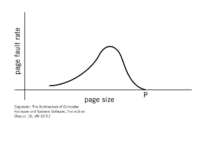
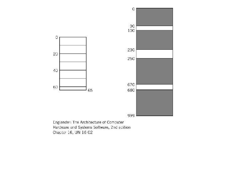
Figure 16. 22 Internal fragmentation
Figure 16. 23 Scan scheduling algorithm Source: Copyright 1971 International Business Machines Corporation. Reprinted with permission from IBM Systems Journal, Vol. 10, No 3.
Figure 16. 24 Comparison of different disk algorithms. Source: A. Silberschatz/ J. Petterson/ P. Galvin, Operating Systems Concepts, Fifth Edition. © 1998 by John Wiley and Sons, Inc. Reprinted by permission of John Wiley & Sons, Inc.
Figure 16. 24 (continued)
Figure 16. 25 The access for a networked operating system
Figure 16. 26 A familiar deadlock situation
Figure 16. 27 Java virtual machine