Fields and forces Topic 6 3 Magnetic force


, l")


- Slides: 51
Fields and forces Topic 6. 3: Magnetic force and field
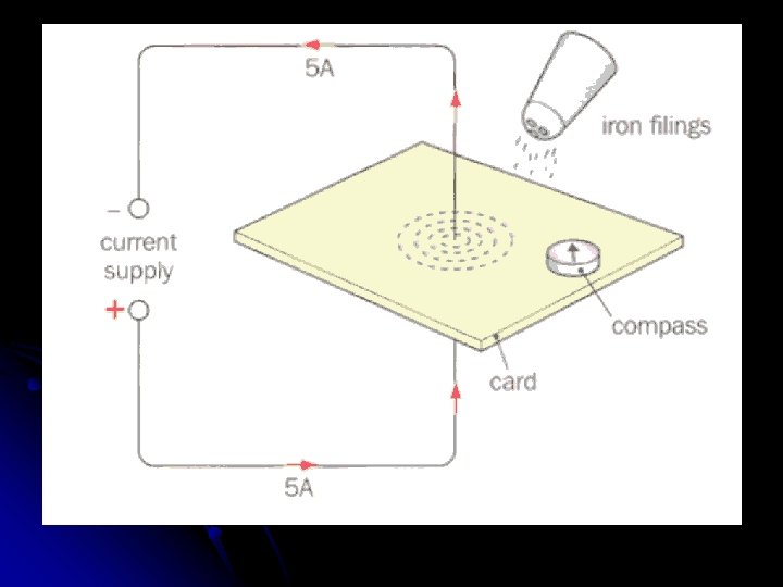
The magnetic field around a long straight wire The diagram shows a wire carrying a current of about 5 amps l If you sprinkle some iron filings on to the horizontal card and tap it gently, the iron filings will line up along the lines of flux as shown. l
You can place a small compass on the card to find the direction of the magnetic field. l With the current flowing up the wire, the compass will point anti‑clockwise, as shown. l What will happen if you reverse the direction of the current? l
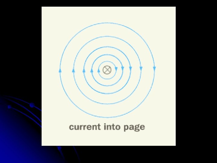
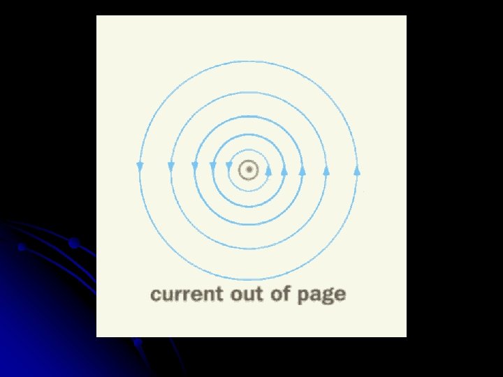
The diagrams show the magnetic field as you look down on the card l Imagine the current direction as an arrow. l When the arrow moves away from you, into the page, you see the cross (x) of the tail of the arrow. l As the current flows towards you, you see the point of the arrow ‑ the dot in the diagram. l
l Can you see that the further from the wire the circles are, the more widely separated they become? What does this tell you? The flux density is greatest close to the wire. l As you move away from the wire the magnetic field becomes weaker. l
l l l The right‑hand grip rule gives a simple way to remember the direction of the field: imagine gripping the wire, so that your right thumb points in the direction of the current. your fingers then curl in the direction of the lines of the field:
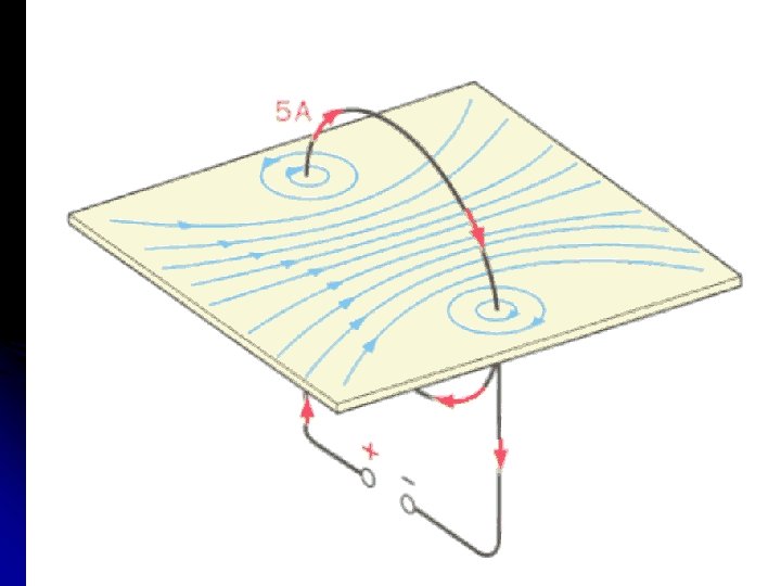
The magnetic field of a flat coil The diagram shows a flat coil carrying electric current: l Again, we can investigate the shape and direction of the magnetic field using iron filings and a compass. l
Close to the wire, the lines of flux are circles. l Can you see that the lines of flux run anti‑clockwise around the left side of the coil and clockwise around the right side? l What happens at the centre of the coil? l The fields due to the sides of the coil are in the same direction and they combine to give a strong magnetic field. l How would you expect the field to change, if the direction of the current flow around the coil was reversed? l
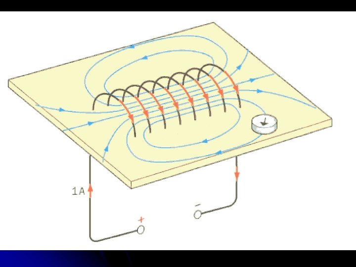
The magnetic field of a solenoid A solenoid is a long coil with a large number of turns of wire. l Look at the shape of the field, revealed by the iron filings. l Does it look familiar? l
l l l The magnetic field outside the solenoid has the same shape as the field around a bar magnet. Inside the solenoid the lines of flux are close together, parallel and equally spaced. What does this tell you? For most of the length of the solenoid the flux density is constant. The field is uniform and strong.
l If you reverse the direction of the current flow, will the direction of the magnetic field reverse?
l A right‑hand grip rule can again be used to remember the direction of the field, but this time you must curl the fingers of your right hand in the direction of the current as shown:
Your thumb now points along the direction of the lines of flux inside the coil. . . towards the end of the solenoid that behaves like the N‑pole of the bar magnet. l This right‑hand grip rule can also be used for the flat coil. l
Magnetic Forces – on Wires l l A wire carrying a current in a magnetic field feels a force. A simple way to demonstrate this is shown in the diagram
The two strong magnets are attached to an iron yoke with opposite poles facing each other. l They produce a strong almost uniform field in the space between them. l What happens when you switch the current on? l The aluminium rod AB feels a force, and moves along the copper rails as shown. l
l Notice that the current, the magnetic field, and the force, are all at right angles to each other. What happens if you reverse the direction of the current flow, or turn the magnets so that the magnetic field acts downwards? l In each case the rod moves in the opposite direction. l
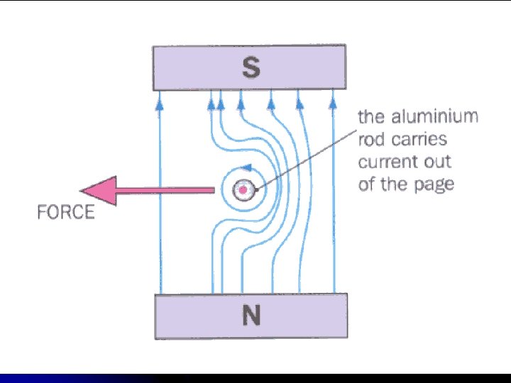
Why does the aluminium rod move? l The magnetic field of the permanent magnets interacts with the magnetic field of the current in the rod. l Imagine looking from end B of the rod. l The diagram shows the combined field of the magnet and the rod l
l l l The lines of flux behave a bit like elastic bands. Can you see that the wire tends to be catapulted to the left? You can use Fleming's left‑hand rule to predict the direction of the force. You need to hold your left hand so that the thumb and the first two fingers are at right angles to each other as shown:
If your First finger points along the Field direction (from N to S), l and your se. Cond finger is the conventional Current direction (from + to ‑), l then your Thumb gives the direction of the Thrust (or force). l
Calculating the Force Experiments like this show us that the force F on a conductor in a magnetic field is directly proportional to: l the magnetic flux density B l the current I, l and the length L of the conductor in the field. l
l In fact:
l l l This equation applies when the current is at 90° to the field. Does changing the angle affect the size of the force? Look at the wire OA in the diagram, at different angles:
l l When the angle θ is 90° the force has its maximum value. As θ is reduced the force becomes smaller. When the wire is parallel to the field, so that θ is zero, the force is also zero. In fact, if the current makes an angle θ to the magnetic field the force is given by:
Notice that: when θ = 90°, sin θ = 1, l and F = B I L as before. l when θ = 0°, sin θ = 0, l and F = 0, as stated above. l The size of the force depends on the angle that the wire makes with the magnetic field, but the direction of the force does not. l The force is always at 90° to both the current and the field. l
Magnetic flux density B and the tesla We can rearrange the equation F = B I L to give: l B = F /IL l What is the value of B, when I = 1 A and L = 1 m? l In this case, B has the same numerical value as F. l
l l l This gives us the definition of B: The magnetic flux density B, is the force acting per unit length, on a wire carrying unit current, which is perpendicular to the magnetic field. The unit of B is the tesla (T). Can you see that: 1 T = 1 N A‑ 1 m‑ 1 ? The tesla is defined in the following way: A magnetic flux density of 1 T produces a force of 1 N on each metre of wire carrying a current of 1 A at 90° to the field.
Magnetic Forces – on Charges l l l A charged particle feels a force when it moves through a magnetic field. What factors do you think affect the size of this force? The force F on the particle is directly proportional to: the magnetic flux density B, the charge on the particle Q, and the velocity v of the particle.
l When the charged particle is moving at 90° to the field, the force can be calculated from:
l l l In which direction does the force act? The force is always at 90° to both the current and the field, and you use Fleming's left‑hand rule to find its direction. (Note: the left‑hand rule applies to conventional current flow. ) A negative charge moving to the right, has to be treated as a positive charge moving to the left. You must point your middle finger in the opposite direction to the movement of the negative charge.
This equation applies when the direction of the charge motion is at 90° to the field. l Does changing the angle affect the size of the force? l As θ is reduced the force becomes smaller. l When the direction is parallel to the field, so that θ is zero, the force is also zero. l In fact, if the charge makes an angle θ to the magnetic field the force is given by: l F = Qv. B sin θ l
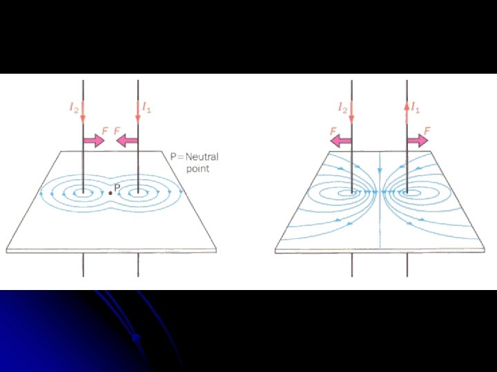
2 Parallel Current-Carrying Wires l l What happens when current is passed along two strips of foil as shown below? The strips bend, as they attract or repel each other. Two parallel, current‑carrying wires exert equal, but opposite forces on each other. Look carefully at these forces, and the resultant magnetic fields around the wires.
The Rules currents flowing in the same direction attract l currents flowing in opposite directions repel. l
l How do these forces arise? l The diagram shows the anti‑clockwise field around wire X:
Wire Y is at 90° to this field, and so it experiences a force. l Apply Fleming's left‑hand rule to wire Y l Do you find that the force on wire Y is to the left, as shown? l
l l l l What is the size of the force? Notice that the wires are a distance r apart. Wire X carries a current Il. Wire Y carries a current I 2. What is the flux density B at wire Y, due to the current Il in X? From B = μ 0 I 1/2πr What is the force F on a length L of wire Y? From F = BI 2 L If we use the first equation to replace B in the second equation
Defining the Ampere The unit of current, the ampere, is defined in terms of the force between two currents. l When two long wires are parallel, and placed 1 metre apart in air, and if the current in each wire is 1 ampere, then the force on each metre of wire is 2 x 10‑ 7 N. l
Therefore l Thus, one ampere is defined as that current flowing in each of two infinitely‑long parallel wires of negligible cross‑sectional area separated by a distance of one metre in a vacuum that results in a force of exactly 2 x 10‑ 7 N per metre of length of each wire.
The Magnetic Field Due to Currents The magnetic field intensity or magnetic induction or magnetic flux density is given the symbol B and it has the units of tesla T l It is a vector quantity. l
For a Long Straight Conductor l The strength of the magnetic field B at any point at a perpendicular distance r from a long straight conductor carrying a current I is given by where μ 0 = 4π x 10 -7 T m A-1 is a constant called the permeability of free space.
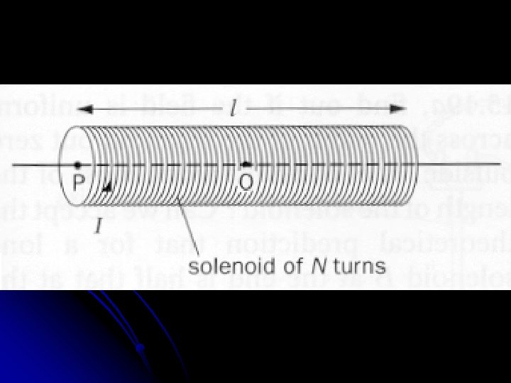
For a Solenoid l l If the solenoid has N turns, length L and carries a current I, the flux density B at a point O on the axis near the centre of the solenoid, is found to be given by B = μ 0 N I / L
l Or B = μ 0 n. I where n = N / L = number of turns per unit length. l B thus equals μ 0 , multiplied by the ampere‑turns per metre. l
The Nature of the Solenoid Core Be aware that the nature of the solenoid core has an affect on B l An iron core concentrates the magnetic field thus making B greater. l If a steel core is used it is not turn-off-able l An electromagnet is good because it can be turned on and off, and can have its strength varied. l