Field Emission Displays The future of display technology


 • Geissler Tubes (1855) • First CRT oscilloscope invented 40")
 • James Fergason produced")
 • Prototype for")


 Low power (5 W/in)")

 High contrast (10000: 1)")
 Large Viewing")


- Slides: 23
Field Emission Displays The future of display technology? Prepared By: Ryan Michaud Adam Neale Andrei Iakimtchik Date: March 27 th, 2007.
Presentation Outline History of display technology Current display alternatives How FEDs work Companies working on FED Difficulties with FED Future of FED displays
History of Display Technology Cathode Ray Tube 1950’s Liquid Crystal Displays 1970’s Field Emission Displays 1980’s
Cathode Ray Tubes (CRT) • Geissler Tubes (1855) • First CRT oscilloscope invented 40 years later • Commercially practical CRT made by Allen Du. Mont (1931)
Liquid Crystal Display • Liquid Crystalline materials discovered (1880 s) • James Fergason produced first practical LCD display (1967) • Epson introduced first color LCD TV 2” in diagonal (1985)
Plasma Display Panel • Plasma identified by William Crookes (1879 s) • Prototype for PDP introduced at University of Illinois (1964) • Fujitsu introduced first 42” color PDP (1997)
Technology Comparison CRT • Vacuum tube with phosphorcoated screen • Cathode emits electrons to be accelerated by the anode • Deflectors guide the electron beams • Electrons excite phosphor molecules to produce light
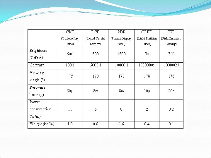
Technology Comparison cont’d CRT Advantages Good color representation Large viewing angle Fast response time (50 µs) Low price Multiple resolutions Shortcomings Large and bulky (2 kg/in) Flicker causes eye strain High power (11 W/in)
Technology Comparison cont’d LCD • A layer of liquid crystalline sandwiched between 2 glass layers with polarizer • Light generated behind the screen, passed through • Applied voltage controls the crystalline orientation
Technology Comparison cont’d LCD Advantages Light weight (0. 6 kg/in) Low power (5 W/in) Less eye strain High brightness (500 Cd/m 2) Shortcomings Small viewing angle Slow response time (8 ms) Weaker contrast & color
Technology Comparison cont’d PDP • Two layers of glass with pixel array in between • Each pixel contains a mix of neon and xenon gas • Current is passed through a pixel to ionize gas, and emit UV radiation • UV rays excites phosphorcoated layer of glass to generate light
Technology Comparison cont’d PDP Advantages High brightness (1000 Cd/m 2) High contrast (10000: 1) Large viewing angle Shortcomings More power vs LCD (8 W/in) Burn-in effect Size limitation (>40”) Slow response time
FED: The Best of Both Worlds Promised Advantages Very light (100 g/in) Large Viewing angle (178 o) Extremely fast (20 ns) Low power (0. 2 W/in) High contrast (10 x PDP) No flicker No dead pixels
How FED Works? Array of mini-CRTs
Technology Options - SED “Surface-conduction electron emitter display” Joint venture between Toshiba and Canon
Technlogy Options - Spindt emitters are tiny cones that create a very high charge density Alignment of the cone and gate is critical
Technology Options - CNT Carbon nanotubes as electron source
Companies Researching FED Canon and Toshiba joint venture in SED Sony promises Spindt-type FED display in 2009 Samsung is researching CNTs, Applied Nanotech Inc. have made a 25” display
Challenges: Technical Problems Fluctuations in emission current Low cost manufacturing methods Developing for large areas Tip damage High vacuum levels required
Dropping LCD prices LCD panels are dropping in cost while increasing in quality
Hope for FED Displays The success of FEDs depends on: Cost Quality Timing Technologically advantageous product suffers from poor timing
Questions?