Feedback System Design Alessandro Drago Super B Meeting

Feedback System Design Alessandro Drago Super. B Meeting 26 -30 January 2000 SLAC

Main Topics • • • Super. B parameters for feedback design Design general consideration R & D main list Scalability Innovation Conclusion

Super. B Parameters From M. Biagini Talk @ Elba’ 08
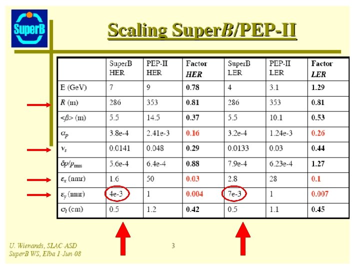

Super. B feedback parameters FB Sampling frequency 476 MHz Harmonic number 2850 Revolution period ~6 us Stored bunches ~1250 (2500) Ph-1 ( Ph-2) Bucket length ~2 ns Ph-1 (ph-2) bunch spacing ns HER/LER 1. 26 (. 63) m Synchrotron frequency ~2. 35/2. 2 k. Hz Longitudinal damping time nx, y HER/LER ~20 ms Betatron frequency 86. 8/90. 2 k. Hz Transverse damping time 40 ms Transv. feedback expected damping time >120 (> 20 turns) us Power amplifier (long. ) 4 x 250 W Power amplifier (trasv. ) 2 x 500 W Trasverse kickers (1 x. V, 1 x. H) 2 -ports Stripline type Longitudinal kicker 4 -ports Cavity type 0. 0141/0. 0133 0. 52/. 54 (? ? ? )

Considerations on H • H, harmonic number=2850 • Still if the stored bunches will be ~1250 (PH 1) & ~2500 (PH 2) to let ion clearing gaps, from a feedback point of view all buckets (2850=H) have to be processed • H=2850 = 2*1425 =2*5*285=2*5*5*57 that is not exactly a wonderful number for FB’s • 1056 dsp: 1056=2*2*2*3*11 • DAFNE_H=120=2*2*2*3*5 • PEPII_H=3492 [with revolution period 7. 336 us ] • 3492 = 1746*2 = 2*2*3*3*97 • In conclusion, for H, highly composed numbers are better than prime numbers

Key points for starting to write a TDR for b-b-b feedback system • • • Innovation Costs Manpower for design Design duration (on 5 - 8 years timescale) Design robustness /self & beam diagnostics Compatibility for new upgrade Flexibility Scalability Maintenance & manpower necessary for maintenance

Key points for starting TDR / 2 • Consequences: – Design based on last version components – Design based on stable (popular) components – Recycle what doesn’t need changes – Unified technology choices as much as possible – Scale savings – Easy interface for not expert operators

Key points for starting TDR / 3 • Consequences of second orders: – Every design based on old FPGA (as i. Gp with V-II) should migrate to last version FPGA (as Xilinx V 5) – Unified technology choices lead to possibly use same tools, parts or designs for similar systems: • • • Transverse feedback Longitudinal feedback Fast IP feedback Timing/injection system (pulse generator) Low level RF 1 -D Bunch-by-bunch and turn-by-turn diagnostics, as for example transverse and longitudinal dimension/position detectors • 2 D Bunch-by-bunch and turn-by-turn diagnostics, as for example profile monitor, etc.

Design robustness • Self diagnostics: internal efficient tools to identify quickly correct operation of every subsystem • Easy timing procedures • Beam diagnostics, in particular instability grow rate measurements • Easy access for non expert operators

e+ instability grow rates versus Δνx in PS 1 -PS 2 and RCR OPTICS: • Collision mode m = -1 (blue) • Δνx = + 0. 5 (PS 1÷PS 2) νx = νy mode m = 0 (red) • Δνx = + 1. 0 (0. 5 in PS 1÷PS 2 0. 5 in RCR) νx = νy mode m = -1 (cyan) This is to study the e+ instability as a function of the relative phase advance between the WGLs

In the past years, troubles were much smaller!!! Hor. e+ grow rates, August 4, 2005 Hor. e+ grow rates, 2004

e+ instability grow rates versus orbit in the main ring dipoles • The orbit variation is performed changing the RF frequency and then compensating the beam energy

e+ instability grow rates versus orbit in the main ring dipoles • The orbit variation shows important differences from the point of view of understanding the instability source • but not to solve completely the e+ current threshold

Scalability • Double feedback in the same oscillation plane to use at the best the power output • A proved example of the scalability advantages • Possibility to have and manage easily more than one feedback in a single oscillation plane • Capability to damp coherent high order modes even if faster than foreseen

• New e+ Transverse Horizontal Feedback • • • The damping times of the two feedbacks add up linearly Damping time measured: ~100 ms-1 (1 FBKs) fb damps in 30 revolution periods (~10 us) ~200 ms-1 (2 FBKs) fb damps in 15 revolution periods (~ 5 us) The power of the H FBK has been doubled

Hybrid Kicker horizontal fdbk e+ ring old pulser e- ring old pulser
![Single horizontal feedback: I=560 m. A, mode -1 [=119] , grow=34. 5 (ms-1), damp=-127(ms-1)](http://slidetodoc.com/presentation_image_h2/52d1bec50ca0ef73869bfe95f0a3709a/image-18.jpg "Single horizontal feedback: I=560 m. A, mode -1 [=119] , grow=34. 5 (ms-1), damp=-127(ms-1)")
Single horizontal feedback: I=560 m. A, mode -1 [=119] , grow=34. 5 (ms-1), damp=-127(ms-1)
![Double horizontal feedback: I=712 m. A, mode -1 [=119] , grow=43. 7 (ms-1), damp=-233](http://slidetodoc.com/presentation_image_h2/52d1bec50ca0ef73869bfe95f0a3709a/image-19.jpg "Double horizontal feedback: I=712 m. A, mode -1 [=119] , grow=43. 7 (ms-1), damp=-233")
Double horizontal feedback: I=712 m. A, mode -1 [=119] , grow=43. 7 (ms-1), damp=-233 (ms-1) Damping time in 4. 3 microsecond i. e. in ~13 revolution turns

Grow rates at higher e+ current, instability controlled by 2 feedback: the unstable mode changes becoming slower! m=-2 m =1 m=-3 The beam current does not seem limited by the horizontal instability

Innovation
 R&D list")
R&D feedback for low emittance accelerator (proposed in July 08 Mini. Mac) R&D list includes: 1) very low noise analog front end @ n*RF [n=3? ] 2) maintain low cross-talk between adjacent bunches under 40 d. B (better 60 d. B) in front end 3) dual separated timing to pilot the backend power stage 4) digital processing unit with high dynamic range (12/16 bits) > 60 d. B 5) “dual gain” approach to minimize residual beam motion and feedback noise on the beam [in digital processing unit] 6) integrated beam-feedback model with easy code and parameter download to digital processing unit

Considering a feedback upgrade for low emittance accelerators - - Feedback are active system and can have strong negative impact on very low emittance beams The basic ideas of the upgrades consist in making the noise in the feedback loop as low as possible, and this means: a) Filtering at the best the external noise, i. e. coming or generated outside the feedback b) Reducing the internal noise, i. e. the noise coming from parts in the feedback system c) Reduce the crosstalk between bunch signals

R & D areas • Analog R&D: Front End / Back End / transverse /longitudinal • Digital processing unit R&D • Beam/feedback Model R&D for coefficient generation/maintenance • other important design areas: – Power amplifiers R&D: not strictly necessary but the high cost of commercial power devices could justify a R&D – Longitudinal & transverse kickers – Beam signal pickups

The dynamic range in DAFNE feedback analog blocks is in the range 78 d. B – 88 d. B

ADC dynamic range versus # of bits • • • 7. 5_bit ADC_= 8_bit ADC _ = 10_bit ADC _= 12_bit ADC _= 14_bit ADC _= 45. 15 d. B } very poor dyn. range ! 48. 16 d. B 60. 20 d. B 72. 25 d. B 84. 29 d. B [best value considering the analog blocks!] • 15_bit ADC _= 90. 31 d. B • 16_bit ADC = 96. 33 d. B • 24_bit ADC = 144. 49 d. B • Note: in general at least 0. 5 bit (= 3 d. B) is not effective in the conversion

A factor liming the effectiveness of the ADC is the sampling clock jitter. I can suppose that a realistic value of the RMS jitter for the timing signal will be ~0. 5 ps This value must be included in Super. B Timing specifications • In this case (yellow trace), the ADC dynamic range should be better than 60 d. B (12 bits)

FIR • The core of a feedback digital processing unit is the FIR filter (=Finite Impulse Response filter) • An FIR filter can have any kind of coefficients and transfer functions but the output y is always built as y = sumi (ci*xi) • i = number of taps (of the filter) • ci = “static” but downloadable coefficients • xi = previuos i input values for each bunches
![2001 VIRTEX-II [used in i. GP]](http://slidetodoc.com/presentation_image_h2/52d1bec50ca0ef73869bfe95f0a3709a/image-29.jpg "2001 VIRTEX-II [used in i. GP]")
2001 VIRTEX-II [used in i. GP]

• Virtex-5 has 1056 DSP 48 and 550 MHz clock speed

Ready for R&D: a Xilinx board with 288 digital signal processors inside
 is built around")
• The last version of feedback system (the “i. Gp”) is built around a Virtex-II FPGA by Xilinx • Virtex-II, aging ~10 years, has 168 multiplier blocks, as shown in the Xilinx table below • The internal clock speed is 420 MHz

Conclusions • Feedback systems needs internal and beam diagnostics tools • The instability grow rates measured by FB show a good agreement with e-cloud model and simulations • It is possible manage more power in the feedbacks installing as many systems as necessary • Two separate feedback systems for the same oscillation plane work in perfect collaboration doubling the damping time • DAFNE feedback damping time is 4. 3 microsecond i. e. ~13 revolution turns, this value can be used to design the Super. B feedback system
- Slides: 33