FEEDBACK IN AMPLIFIERS CONCEPT OF FEEDBACK WHAT IS

FEEDBACK IN AMPLIFIERS CONCEPT OF FEEDBACK

WHAT IS FEEDBACK • The feedback-amplifier can be defined as an amplifier which has feedback lane that exists between o/p to input. In this type of amplifier, feedback is the limitation which calculates the sum of feedback given in the following amplifier. The feedback factor is the ratio of the feedback signal and the input signal.

Amplifiers Feedback • An amplifier circuit simply increases the signal strength. But while amplifying, it just increases the strength of its input signal whether it contains information or some noise along with information. This noise or some disturbance is introduced in the amplifiers because of their strong tendency to introduce hum due to sudden temperature changes or stray electric and magnetic fields. Therefore, every high gain amplifier tends to give noise along with signal in its output, which is very undesirable. • The noise level in the amplifier circuits can be considerably reduced by using negative feedback done by injecting a fraction of output in phase opposition to the input signal.

Principle of Feedback Amplifier A feedback amplifier generally consists of two parts. They are the amplifier and the feedback circuit. The feedback circuit usually consists of resistors. The concept of feedback amplifier can be understood from the following figure.

• From the following figure, the gain of the amplifier is represented as A. the gain of the amplifier is the ratio of output voltage Vo to the input voltage Vi. the feedback network extracts a voltage Vf = β Vo from the output Vo of the amplifier. • This voltage is added for positive feedback and subtracted for negative feedback, from the signal voltage Vs. Now, •

FEEDBACK AMPLIFIER

From the above figure, the gain of the amplifier is represented as A. the gain of the amplifier is the ratio of output voltage Vo to the input voltage Vi. the feedback network extracts a voltage Vf = β Vo from the output Vo of the amplifier. This voltage is added for positive feedback and subtracted for negative feedback, from the signal voltage Vs. Now, Vi=Vs+Vf=Vs+βVo Vi=Vs−Vf=Vs−βVo The quantity β = Vf/Vo is called as feedback ratio or feedback fraction. Let us consider the case of negative feedback. The output Vo must be equal to the input voltage (Vs - βVo) multiplied by the gain A of the amplifier. Hence,
A=Vo Or AVs−AβVo=Vo Or AVs=Vo(1+Aβ) Therefore, Vo. Vs=A 1+Aβ Let Af be the overall")
(Vs−βVo)A=Vo Or AVs−AβVo=Vo Or AVs=Vo(1+Aβ) Therefore, Vo. Vs=A 1+Aβ Let Af be the overall gain (gain with the feedback) of the amplifier. This is defined as the ratio of output voltage Vo to the applied signal voltage Vs, i. e. , Af=Outputvoltage. Inputsignalvoltage=Vo. Vs. Af=Outputvoltage. Inputsignalvoltage= Vo. Vs So, from the above two equations, we can understand that, The equation of gain of the feedback amplifier, with negative feedback is given by Af=A 1+Aβ The equation of gain of the feedback amplifier, with positive feedback is given by Af=A 1−Aβ These are the standard equations to calculate the gain of feedback amplifiers.

Types of Feedbacks The process of injecting a fraction of output energy of some device back to the input is known as Feedback. It has been found that feedback is very useful in reducing noise and making the amplifier operation stable. Depending upon whether the feedback signal aids or opposes the input signal, there are two types of feedbacks used.

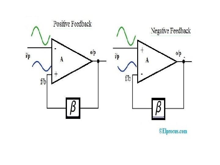
Positive Feedback The feedback in which the feedback energy i. e. , either voltage or current is in phase with the input signal and thus aids it is called as Positive feedback. Both the input signal and feedback signal introduces a phase shift of 180 o thus making a 360 o resultant phase shift around the loop, to be finally in phase with the input signal.

Though the positive feedback increases the gain of the amplifier, it has the disadvantages such as Increasing distortion Instability It is because of these disadvantages the positive feedback is not recommended for the amplifiers. If the positive feedback is sufficiently large, it leads to oscillations, by which oscillator circuits are formed.

Negative Feedback The feedback in which the feedback energy i. e. , either voltage or current is out of phase with the input and thus opposes it, is called as negative feedback. In negative feedback, the amplifier introduces a phase shift of 180 o into the circuit while the feedback network is so designed that it produces no phase shift or zero phase shift. Thus the resultant feedback voltage Vf is 180 o out of phase with the input signal Vin.

Though the gain of negative feedback amplifier is reduced, there are many advantages of negative feedback such as 1. Stability of gain is improved 2. Reduction in distortion 3. Reduction in noise 4. Increase in input impedance 5. Decrease in output impedance Increase in the range of uniform application It is because of these advantages negative feedback is frequently employed in amplifiers.

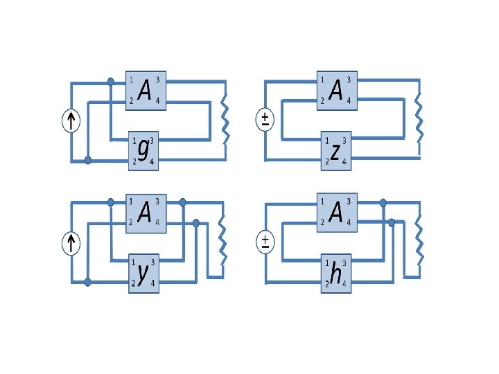
Feedback Amplifier Topologies There are four basic amplifier topologies for connecting the feedback signal. Both the current as well as voltage can be feedback toward the input in series otherwise in parallel.

ØVoltage Series. Feedback Amplifier ØVoltage Shunt Feedback Amplifier ØCurrent Series Feedback Amplifier ØCurrent Shunt Feedback Amplifier
 Voltage Series Feedback Amplifier In this type of circuit, a portion of")
a. ) Voltage Series Feedback Amplifier In this type of circuit, a portion of the o/p voltage can be applied to the input voltage in series through the feedback circuit. The block diagram of the voltage series feedback-amplifier is shown below, by which it is apparent that the feedback circuit is located in shunt by means of the output although in series by means of the input. When the feedback circuit is allied in shunt through the output, then the o/p impedance will be reduced and the i/p impedance is enlarged because of the series connection with the input.
 Voltage Shunt Feedback Amplifier In this type of circuit, a portion of")
b. ) Voltage Shunt Feedback Amplifier In this type of circuit, a portion of the o/p voltage can be applied to the input voltage in parallel with through the feedback circuit. The block diagram of the voltage shunt feedback-amplifier is shown below, by which it is apparent that the feedback circuit is located in shunt by means of the output as well as the input. When the feedback circuit is allied in shunt through the o/p as well as the input, then both the o/p impedance & the i/p impedance will be decreased.
 Current Series Feedback Amplifier In this type of circuit, a portion of")
c. ) Current Series Feedback Amplifier In this type of circuit, a portion of the o/p voltage is applied to the i/p voltage in series through the feedback circuit. The block diagram of the current series feedback -amplifier is shown below, by which it is apparent that the feedback circuit is located in series by means of the output as well as the input. When the feedback circuit is allied in series through the o/p as well as the input, then both the o/p impedance & the i/p impedance will be increased.
 Current Shunt Feedback Amplifier In this type of circuit, a portion of")
d. ) Current Shunt Feedback Amplifier In this type of circuit, a portion of the o/p voltage is applied to the i/p voltage in shunt through the feedback circuit. The block diagram of the current shunt feedbackamplifier is shown below, by which it is apparent that the feedback circuit is located in shunt by means of the output as well as the input. When the feedback circuit is allied in series through the o/p however in parallel with the input, then the o/p impedance will be increased & because of the parallel connection with the i/p, the i/p impedance will be decreased.

Amplifier Characteristics The amplifier characteristics which are affected by various negative feedback are listed in the following table. Feedback Topology Input Resistance Output Resistance Voltage Series Increases Rif = Ri*(1+A*β) Decreases Rof=Ro/(1+A*β) Current Series Increases Rif = Ri*(1+A*β) Increases Rof = Ro*(1+A*β) Current Shunt Decreases Rif = Ri/(1+A*β) Increases Rof = Ro*(1+A*β) Voltage Shunt Decreases Rif = Ri*(1+A*β) Decreases Rof=Ro/(1+A*β)

Advantages and Disadvantages The advantages of this amplifier include the following. The amplifier’s gain can be stabilized by the negative feedback The particular feedback configurations can be increased by the input resistance. Output resistance will be decreased for particular feedback configurations. The operating point is stabilized. The disadvantage of this amplifier is a gain reduction.

- Slides: 24