
Feedback Feedback Taking a portion of the output
Feedback • Feedback: Taking a portion of the output and feeding it back to the input • Positive feedback: Feedback signal is in phase with the input signal – Oscillations (good and bad) – Increase circuit gain • Negative feedback: Feedback signal is out of phase with the input signal – Used in almost all practical amplifiers – Pros: Increased circuit stability against fluctuations (including temp. changes), increased Zin, decreased Zout, decreased signal distortion, higher frequency range for constant gain – Cons: Decreased circuit gain (feedback reduces input)
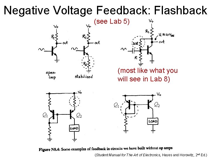
Negative Voltage Feedback: Flashback (see Lab 5) (most like what you will see in Lab 8) Q 1 Q 2 (Student Manual for The Art of Electronics, Hayes and Horowitz, 2 nd Ed. )
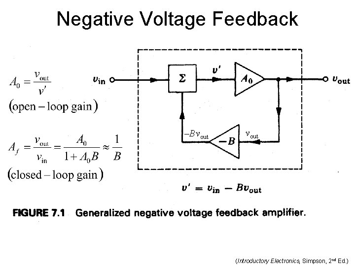
Negative Voltage Feedback –Bvout (Introductory Electronics, Simpson, 2 nd Ed. )
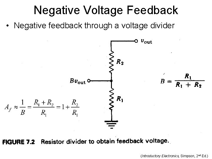
Negative Voltage Feedback • Negative feedback through a voltage divider (Introductory Electronics, Simpson, 2 nd Ed. )
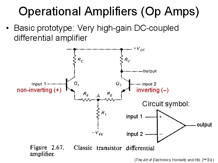
Operational Amplifiers (Op Amps) • Basic prototype: Very high-gain DC-coupled differential amplifier non-inverting (+) inverting (–) Circuit symbol: input 1 output input 2 (The Art of Electronics, Horowitz and Hill, 2 nd Ed. )
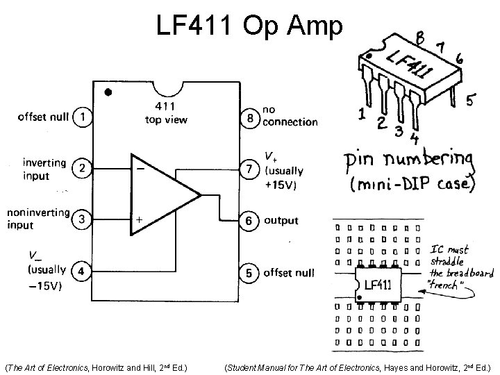
LF 411 Op Amp (The Art of Electronics, Horowitz and Hill, 2 nd Ed. ) (Student Manual for The Art of Electronics, Hayes and Horowitz, 2 nd Ed. )
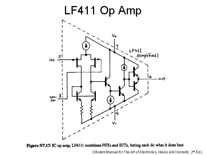
LF 411 Op Amp (Student Manual for The Art of Electronics, Hayes and Horowitz, 2 nd Ed. )
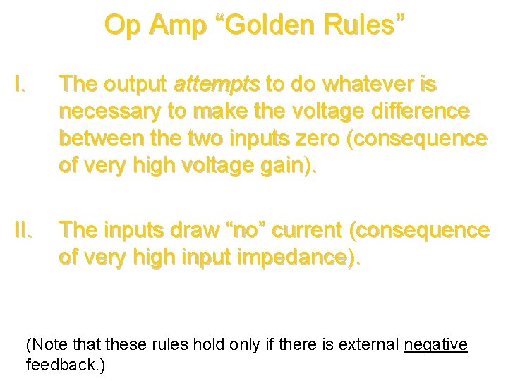
Op Amp “Golden Rules” I. The output attempts to do whatever is necessary to make the voltage difference between the two inputs zero (consequence of very high voltage gain). II. The inputs draw “no” current (consequence of very high input impedance). (Note that these rules hold only if there is external negative feedback. )
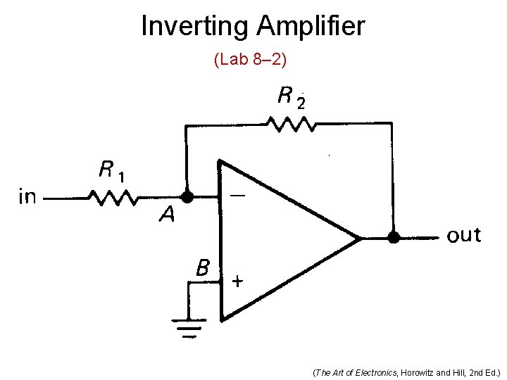
Inverting Amplifier (Lab 8– 2) (The Art of Electronics, Horowitz and Hill, 2 nd Ed. )
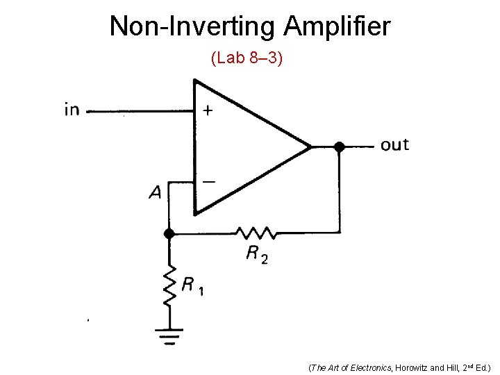
Non-Inverting Amplifier (Lab 8– 3) (The Art of Electronics, Horowitz and Hill, 2 nd Ed. )
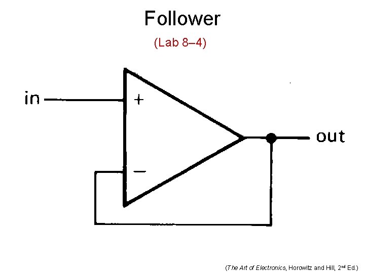
Follower (Lab 8– 4) (The Art of Electronics, Horowitz and Hill, 2 nd Ed. )
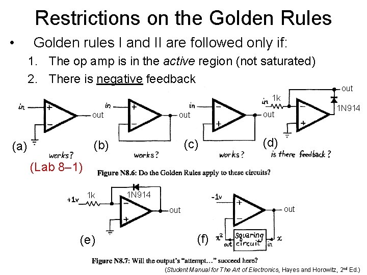
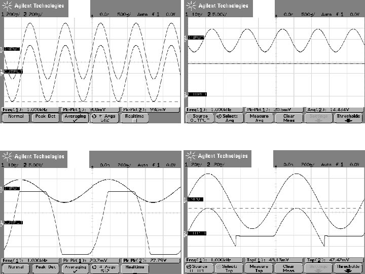
Restrictions on the Golden Rules • Golden rules I and II are followed only if: 1. The op amp is in the active region (not saturated) 2. There is negative feedback out 1 k (c) (b) (a) 1 N 914 out out (d) (Lab 8– 1) 1 k 1 N 914 out (e) (f) (Student Manual for The Art of Electronics, Hayes and Horowitz, 2 nd Ed. )
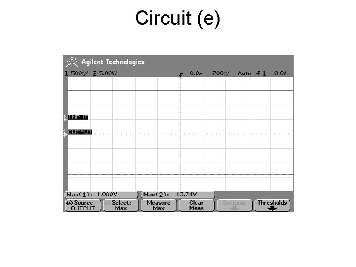
Circuit (e)
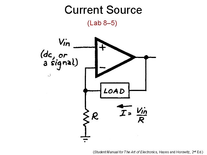
Current Source (Lab 8– 5) (Student Manual for The Art of Electronics, Hayes and Horowitz, 2 nd Ed. )
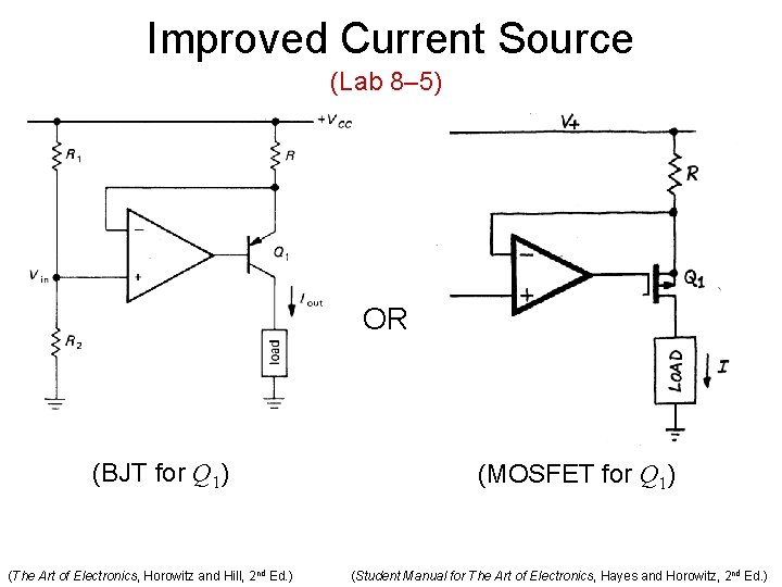
Improved Current Source (Lab 8– 5) OR (BJT for Q 1) (The Art of Electronics, Horowitz and Hill, 2 nd Ed. ) (MOSFET for Q 1) (Student Manual for The Art of Electronics, Hayes and Horowitz, 2 nd Ed. )
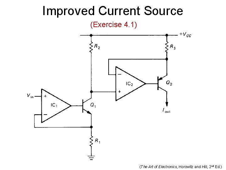
Improved Current Source (Exercise 4. 1) (The Art of Electronics, Horowitz and Hill, 2 nd Ed. )
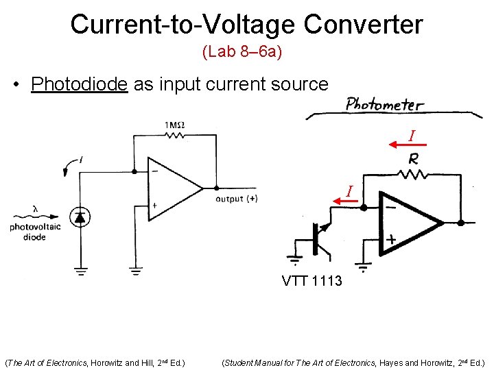
Current-to-Voltage Converter (Lab 8– 6 a) • Photodiode as input current source I I VTT 1113 (The Art of Electronics, Horowitz and Hill, 2 nd Ed. ) (Student Manual for The Art of Electronics, Hayes and Horowitz, 2 nd Ed. )
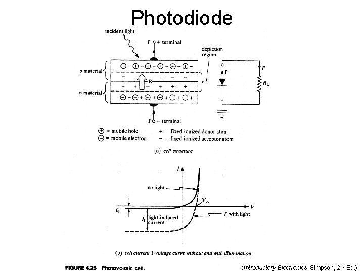
Photodiode (Introductory Electronics, Simpson, 2 nd Ed. )
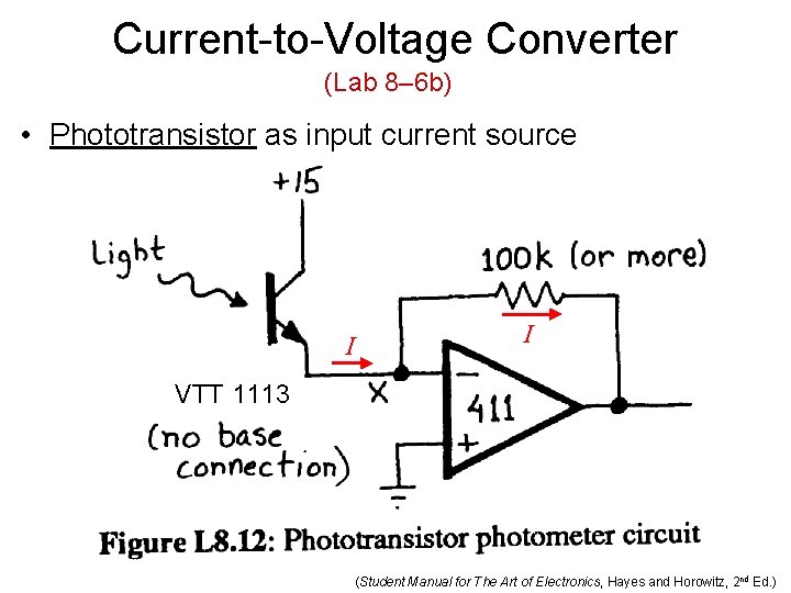
Current-to-Voltage Converter (Lab 8– 6 b) • Phototransistor as input current source I I VTT 1113 (Student Manual for The Art of Electronics, Hayes and Horowitz, 2 nd Ed. )
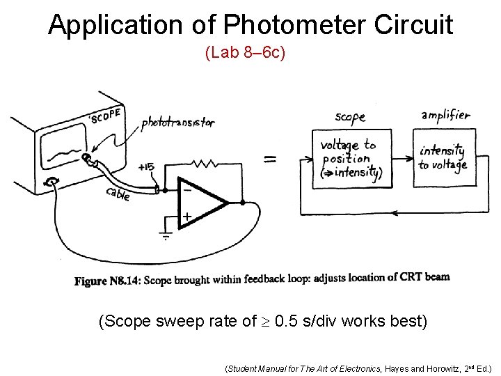
Application of Photometer Circuit (Lab 8– 6 c) (Scope sweep rate of 0. 5 s/div works best) (Student Manual for The Art of Electronics, Hayes and Horowitz, 2 nd Ed. )
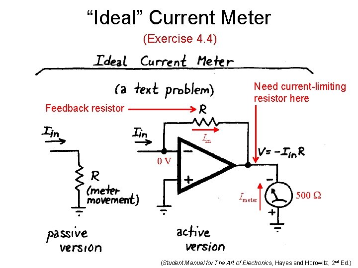
“Ideal” Current Meter (Exercise 4. 4) Need current-limiting resistor here Feedback resistor Iin 0 V Imeter 500 W (Student Manual for The Art of Electronics, Hayes and Horowitz, 2 nd Ed. )
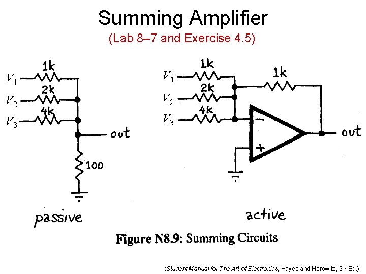
Summing Amplifier (Lab 8– 7 and Exercise 4. 5) V 1 V 2 V 3 (Student Manual for The Art of Electronics, Hayes and Horowitz, 2 nd Ed. )
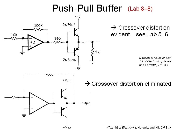
Push-Pull Buffer (Lab 8– 8) Crossover distortion evident – see Lab 5– 6 (Student Manual for The Art of Electronics, Hayes and Horowitz, 2 nd Ed. ) Crossover distortion eliminated (The Art of Electronics, Horowitz and Hill, 2 nd Ed. )
- Slides: 24