
FCC Week 2018 Amsterdam April 9 13 2018
- Slides: 17
FCC Week 2018 Amsterdam, April 9 -13, 2018
FCC-ee Beam Vacuum Concept: the Beam Pipe of FCC-ee Contents • Machine parameters • SR spectra and outgassing loads • Vacuum chamber geometry • Vacuum pumping system • E-cloud mitigation • Expected performance, pressure profiles in the arcs • Machine Detector Interface areas • Summary and conclusions FCC-ee Beam Vacuum Concept: the Beam Pipe of FCC-ee Roberto Kersevan 4 th FCC Week, Amsterdam, 9 -13 April 2018 2
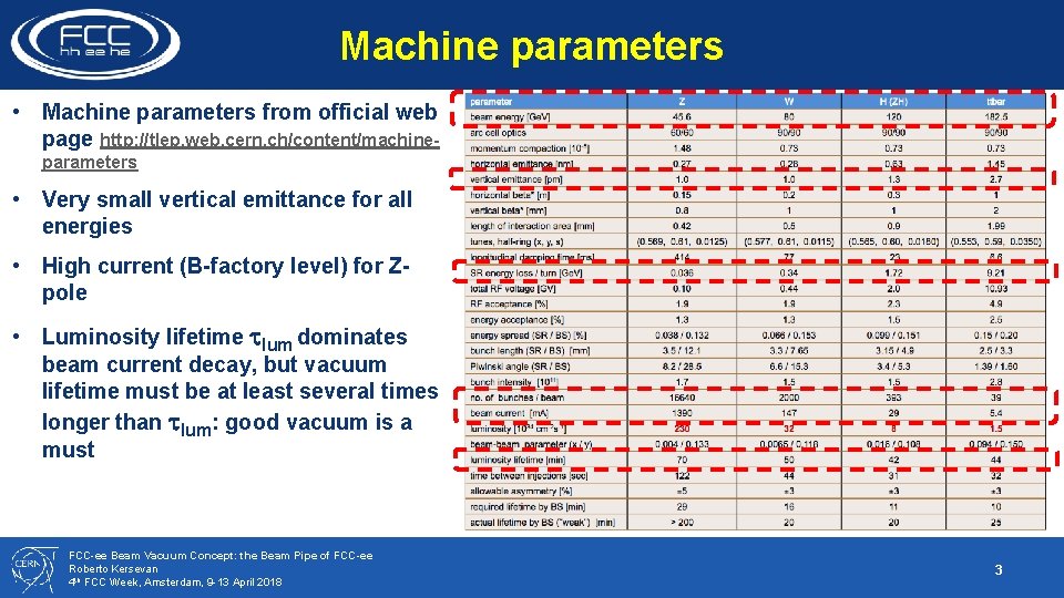
Machine parameters • Machine parameters from official web page http: //tlep. web. cern. ch/content/machineparameters • Very small vertical emittance for all energies • High current (B-factory level) for Zpole • Luminosity lifetime tlum dominates beam current decay, but vacuum lifetime must be at least several times longer than tlum: good vacuum is a must FCC-ee Beam Vacuum Concept: the Beam Pipe of FCC-ee Roberto Kersevan 4 th FCC Week, Amsterdam, 9 -13 April 2018 3
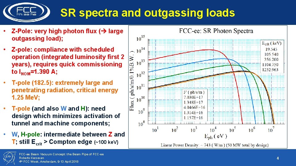
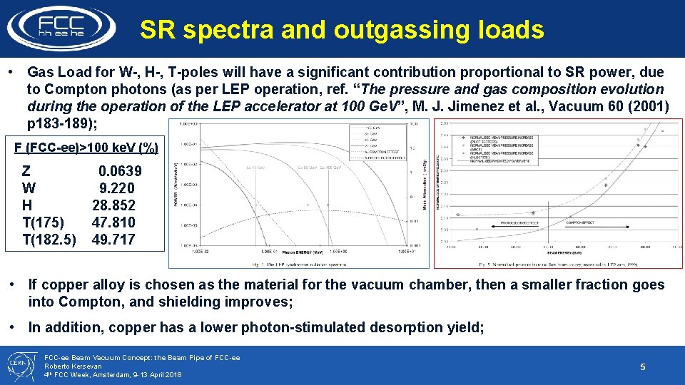
SR spectra and outgassing loads • Z-Pole: very high photon flux ( large outgassing load); • Z-pole: compliance with scheduled operation (integrated luminosity first 2 years), requires quick commissioning to INOM=1. 390 A; • T-pole (182. 5): extremely large and penetrating radiation, critical energy 1. 25 Me. V; • T-pole (and also W and H): need design which minimizes activation of tunnel and machine components; • W, H-pole: intermediate between Z and T; still Ecrit > Compton edge (~100 ke. V) FCC-ee Beam Vacuum Concept: the Beam Pipe of FCC-ee Roberto Kersevan 4 th FCC Week, Amsterdam, 9 -13 April 2018 4
SR spectra and outgassing loads • Gas Load for W-, H-, T-poles will have a significant contribution proportional to SR power, due to Compton photons (as per LEP operation, ref. “The pressure and gas composition evolution during the operation of the LEP accelerator at 100 Ge. V”, M. J. Jimenez et al. , Vacuum 60 (2001) p 183 -189); F (FCC-ee)>100 ke. V (%) Z 0. 0639 W 9. 220 H 28. 852 T(175) 47. 810 T(182. 5) 49. 717 • If copper alloy is chosen as the material for the vacuum chamber, then a smaller fraction goes into Compton, and shielding improves; • In addition, copper has a lower photon-stimulated desorption yield; FCC-ee Beam Vacuum Concept: the Beam Pipe of FCC-ee Roberto Kersevan 4 th FCC Week, Amsterdam, 9 -13 April 2018 5
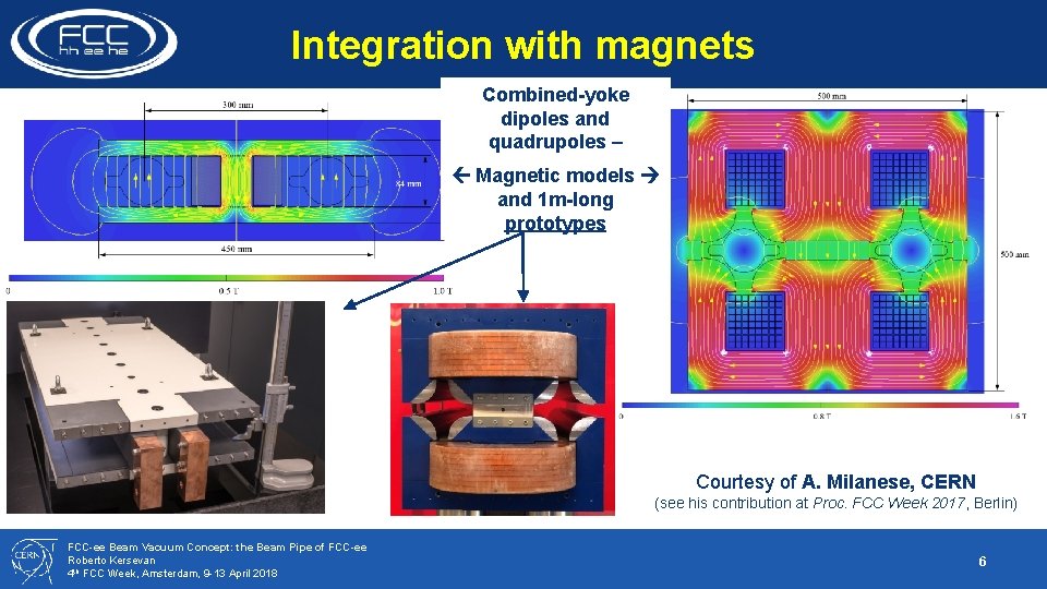
Integration with magnets Combined-yoke dipoles and quadrupoles – Magnetic models and 1 m-long prototypes Courtesy of A. Milanese, CERN (see his contribution at Proc. FCC Week 2017, Berlin) FCC-ee Beam Vacuum Concept: the Beam Pipe of FCC-ee Roberto Kersevan 4 th FCC Week, Amsterdam, 9 -13 April 2018 6
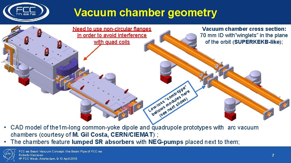
Vacuum chamber geometry Need to use non-circular flanges in order to avoid interference with quad coils Vacuum chamber cross section: 70 mm ID with”winglets” in the plane of the orbit (SUPERKEKB-like); e” p -ty ere b h om les ) c s “ odu lides s o s l m w- ws ext o L llo e n be (se • CAD model of the 1 m-long common-yoke dipole and quadrupole prototypes with arc vacuum chambers (courtesy of M. Gil Costa, CERN/CIEMAT) ; • The chambers feature lumped SR absorbers with NEG-pumps placed next to them; FCC-ee Beam Vacuum Concept: the Beam Pipe of FCC-ee Roberto Kersevan 4 th FCC Week, Amsterdam, 9 -13 April 2018 7
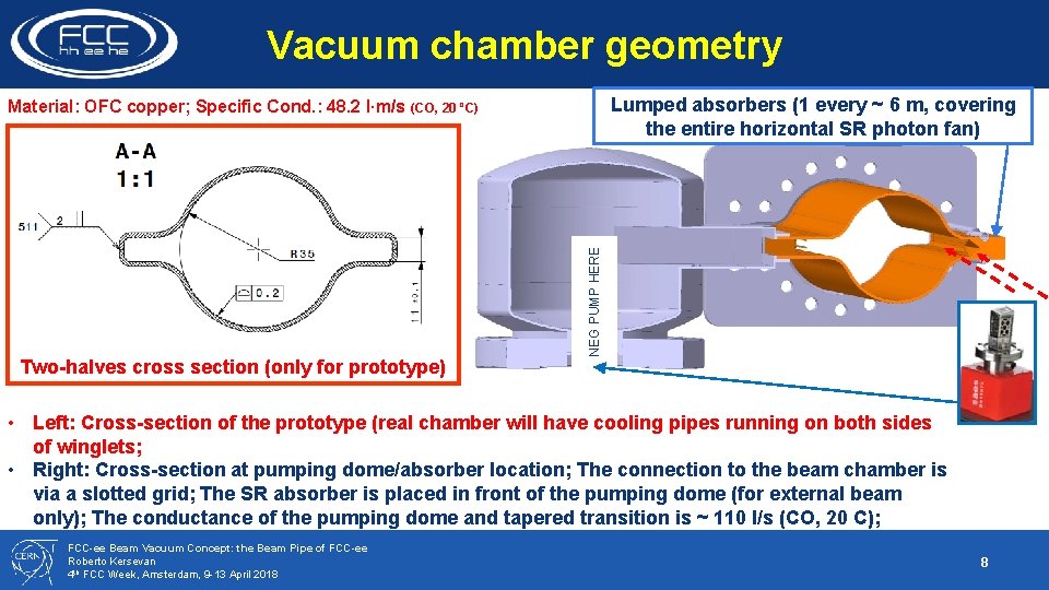
Vacuum chamber geometry Lumped absorbers (1 every ~ 6 m, covering the entire horizontal SR photon fan) Two-halves cross section (only for prototype) NEG PUMP HERE Material: OFC copper; Specific Cond. : 48. 2 l∙m/s (CO, 20 ºC) • Left: Cross-section of the prototype (real chamber will have cooling pipes running on both sides of winglets; • Right: Cross-section at pumping dome/absorber location; The connection to the beam chamber is via a slotted grid; The SR absorber is placed in front of the pumping dome (for external beam only); The conductance of the pumping dome and tapered transition is ~ 110 l/s (CO, 20 C); FCC-ee Beam Vacuum Concept: the Beam Pipe of FCC-ee Roberto Kersevan 4 th FCC Week, Amsterdam, 9 -13 April 2018 8
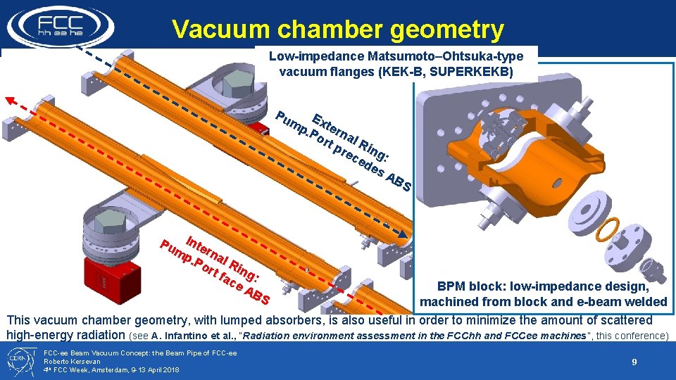
Vacuum chamber geometry Low-impedance Matsumoto–Ohtsuka-type vacuum flanges (KEK-B, SUPERKEKB) Pu mp Exte. Po rna rt p l R rec ing: ed es AB S Pu Inte mp rna. Po l R rt f ing ac : e A BS BPM block: low-impedance design, machined from block and e-beam welded This vacuum chamber geometry, with lumped absorbers, is also useful in order to minimize the amount of scattered high-energy radiation (see A. Infantino et al. , “Radiation environment assessment in the FCChh and FCCee machines”, this conference) FCC-ee Beam Vacuum Concept: the Beam Pipe of FCC-ee Roberto Kersevan 4 th FCC Week, Amsterdam, 9 -13 April 2018 9
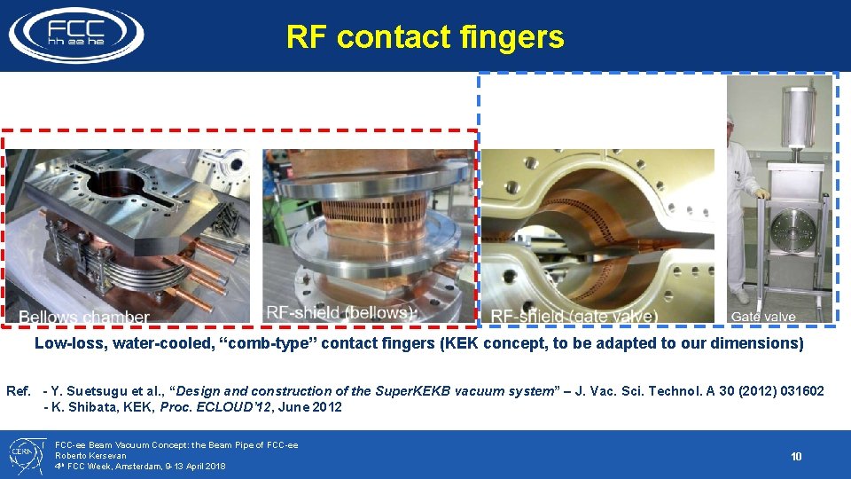
RF contact fingers Low-loss, water-cooled, “comb-type” contact fingers (KEK concept, to be adapted to our dimensions) Ref. - Y. Suetsugu et al. , “Design and construction of the Super. KEKB vacuum system” – J. Vac. Sci. Technol. A 30 (2012) 031602 - K. Shibata, KEK, Proc. ECLOUD’ 12, June 2012 FCC-ee Beam Vacuum Concept: the Beam Pipe of FCC-ee Roberto Kersevan 4 th FCC Week, Amsterdam, 9 -13 April 2018 10
Vacuum pumping system • The common-yoke design for the magnets does not allow us to use a chamber-antechamber design like LEP; the proposed pumping concept is based on a design philosophy combining a reduction of the SRinduced outgassing load thanks to the lumped absorbers, the use of high-speed/high-capacity pumps placed next to the absorbers, and the use of thin-film coatings or surface texturing which would reduce the amount of gas generated by SR photons and avoid the contribution to outgassing of e-cloud multipacting; The proposed, baseline design is the following: • NEG-coating (to reduce photon-stimulated desorption and photo-electron production) • High-capacity lumped NEG pumps (NEXTorr, SAES Getters) One open issue with NEG-coating is its contribution to the longitudinal resistive-wall instability 1; • It is being addressed experimentally now at CERN 2, and will be also tested with SR at the Photon Factory soon 3 1 E. Belli et al. , “Impedance model and single-beam collective effects”, this conference 2 T. Finkley Sinkovits et al. , “Minimum effective thickness for activation and low total electron yield of Ti. Zr. V non-evaporable getter coatings”, this conf. 3 Y. Tanimoto et al. , Photon Factory, KEK (to be published) FCC-ee Beam Vacuum Concept: the Beam Pipe of FCC-ee Roberto Kersevan 4 th FCC Week, Amsterdam, 9 -13 April 2018 11
E-cloud mitigation • As already mentioned, the baseline option is the use of NEG-coatings; it is known to have a low SEY • An experimental research program is underway at CERN in order to determine what minimum thickness of the NEG-coating would be tolerable without affecting the longitudinal resistive-wall instability threshold, providing a sufficiently low secondary electron yield (SEY), and providing also a low photon-stimulated desorption (PSD) yield after repeated saturation/activation cycles. • So far (see refs. 1 and 2 previous slide) 30, 90, and 200 nm-thick coatings have been tested via XPS analysis (oxygen dissolution profiles vs depth), and 4 thermal cycles (activation at 250 C); • The results are encouraging • Plan-B options are: • amorphous carbon • titanium nitride • laser-ablated surface texturing 1 -4 • clearing electrodes 1 O. Malyshev et al. , “A Facility for Studying ESD from NEG Coated Surfaces at Cryogenic Temperatures”, this conf. 2 O. Malyshev et al. , “NEG Coatings and laser surface engineering (LASE) electron cloud mitigation techniques”, this conf. 3 T. Sian et al. , “New LASE surfaces obtained with various lasers and their parameters for e-cloud mitigation”, this conf. 4 R. Valizadeh et al. , “Recent development in Laser ablation surface engineering for reduction of secondary electron yield”, this conf. FCC-ee Beam Vacuum Concept: the Beam Pipe of FCC-ee Roberto Kersevan 4 th FCC Week, Amsterdam, 9 -13 April 2018 12
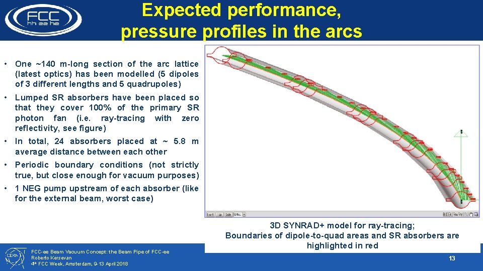
Expected performance, pressure profiles in the arcs • One ~140 m-long section of the arc lattice (latest optics) has been modelled (5 dipoles of 3 different lengths and 5 quadrupoles) • Lumped SR absorbers have been placed so that they cover 100% of the primary SR photon fan (i. e. ray-tracing with zero reflectivity, see figure) • In total, 24 absorbers placed at ~ 5. 8 m average distance between each other • Periodic boundary conditions (not strictly true, but close enough for vacuum purposes) • 1 NEG pump upstream of each absorber (like for the external beam, worst case) FCC-ee Beam Vacuum Concept: the Beam Pipe of FCC-ee Roberto Kersevan 4 th FCC Week, Amsterdam, 9 -13 April 2018 3 D SYNRAD+ model for ray-tracing; Boundaries of dipole-to-quad areas and SR absorbers are highlighted in red 13
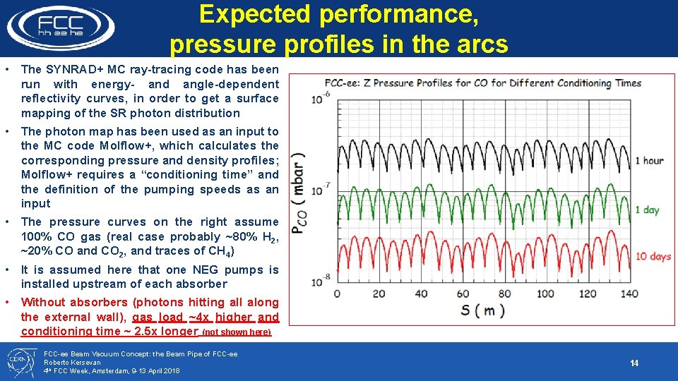
Expected performance, pressure profiles in the arcs • The SYNRAD+ MC ray-tracing code has been run with energy- and angle-dependent reflectivity curves, in order to get a surface mapping of the SR photon distribution • The photon map has been used as an input to the MC code Molflow+, which calculates the corresponding pressure and density profiles; Molflow+ requires a “conditioning time” and the definition of the pumping speeds as an input • The pressure curves on the right assume 100% CO gas (real case probably ~80% H 2, ~20% CO and CO 2, and traces of CH 4) • It is assumed here that one NEG pumps is installed upstream of each absorber • Without absorbers (photons hitting all along the external wall), gas load ~4 x higher and conditioning time ~ 2. 5 x longer (not shown here) FCC-ee Beam Vacuum Concept: the Beam Pipe of FCC-ee Roberto Kersevan 4 th FCC Week, Amsterdam, 9 -13 April 2018 14
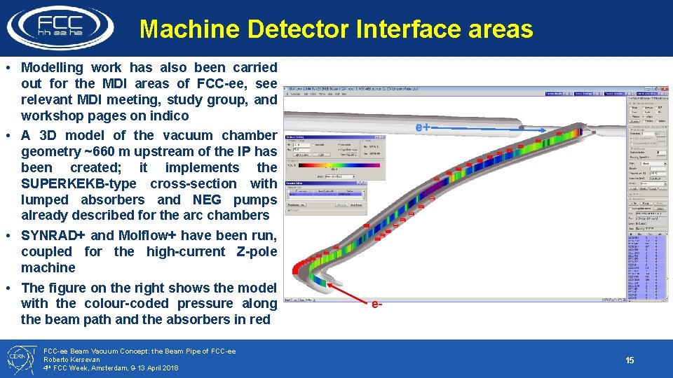
Machine Detector Interface areas • Modelling work has also been carried out for the MDI areas of FCC-ee, see relevant MDI meeting, study group, and workshop pages on indico • A 3 D model of the vacuum chamber geometry ~660 m upstream of the IP has been created; it implements the SUPERKEKB-type cross-section with lumped absorbers and NEG pumps already described for the arc chambers • SYNRAD+ and Molflow+ have been run, coupled for the high-current Z-pole machine • The figure on the right shows the model with the colour-coded pressure along the beam path and the absorbers in red FCC-ee Beam Vacuum Concept: the Beam Pipe of FCC-ee Roberto Kersevan 4 th FCC Week, Amsterdam, 9 -13 April 2018 e+ e- 15
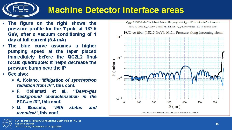
Machine Detector Interface areas • The figure on the right shows the pressure profile for the T-pole at 182. 5 Ge. V, after a vacuum conditioning of 1 day at full current (5. 4 m. A) • The blue curve assumes a higher pumping speed at the taper placed immediately before the QC 2 L 2 finalfocus quadrupole: it helps decrease the pressure bump near the IP • See also: Ø A. Kolano, “Mitigation of synchrotron radiation from IR”, this conf. Ø F. Collamati et al. , “Beam-gas background characterization in the FCC-ee IR”, this conf. Ø M. Boscolo, “MDI status and overview”, this conf. FCC-ee Beam Vacuum Concept: the Beam Pipe of FCC-ee Roberto Kersevan 4 th FCC Week, Amsterdam, 9 -13 April 2018 16
Summary and conclusions 1. 2. 3. 4. 5. 6. Following the developments on the design of the arc magnets and optics, a vacuum chamber cross -section has been chosen It is derived from that successfully implemented in the two rings of SUPERKEKB, with reduced dimensions (70 mm ID circular tube with two small “winglets” in the plane of the orbit) Careful ray-tracing and vacuum considerations have convinced us that a lumped absorber design would improve the vacuum performance and shorten the commissioning time “Thin” NEG-coating is the baseline choice for e-cloud mitigation and in order to shorten the vacuum conditioning due to SR photon irradiation Plan-B e-cloud mitigation options are being considered too: Ti. N, amorphous carbon, LASE texturing, and clearing electrodes Implementation of the same concept in the MDI areas has also been studied: it would generate a low-background at the IP Work to do for the CDR: • Interact with lattice people in order to determine the length of the real chambers (dipoles in lattice have lenghts > 20 m, irrealistic for fabrication and transport) • Full arc model to pass on to FLUKA team for R 2 E and tunnel activation studies FCC-ee Beam Vacuum Concept: the Beam Pipe of FCC-ee Roberto Kersevan 4 th FCC Week, Amsterdam, 9 -13 April 2018 Many thanks to M. Ady, CERN, for support with lattice file conversion and integration into SYNRAD+ code 17