
Fault Tree Analysis Part 4 DigraphBased Fault Tree
Fault Tree Analysis Part 4: Digraph-Based Fault Tree Synthesis Procedure (NFFL and Lapp -Powers Algorithm)
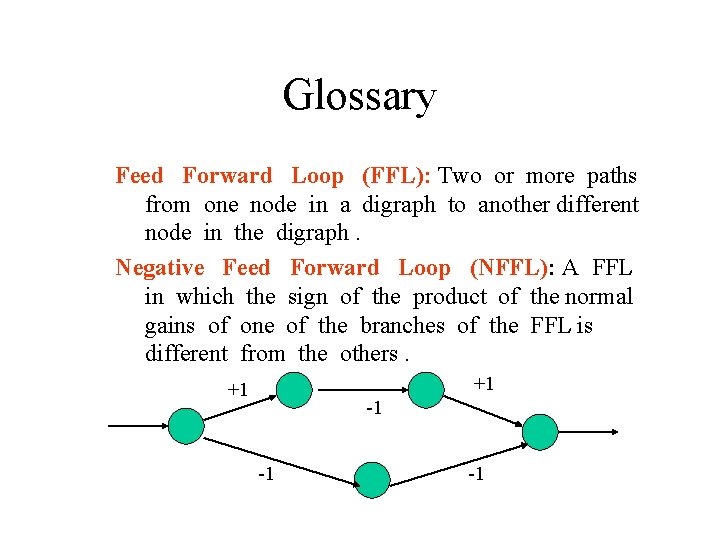
Glossary Feed Forward Loop (FFL): Two or more paths from one node in a digraph to another different node in the digraph. Negative Feed Forward Loop (NFFL): A FFL in which the sign of the product of the normal gains of one of the branches of the FFL is different from the others. +1 +1 -1 -1 -1
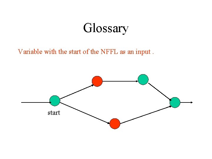
Glossary Variable with the start of the NFFL as an input. start
[Example] HEAT EXCHANGER WITH TEMPERATURE FEEDFORWARD LOOP The process shown in the next figure tries to maintain T 3 at a set temperature by sensing the temperature of stream 1 and changing the flow of cold fluid in stream 7. The top event of fault tree in this example is T 3 (+1).
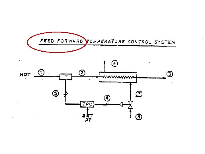

P 6

THE GENERAL FAULT-TREE STRUCTURES FOR NFFL Two Paths on NFFL : (1) T 1 (+1) T 2 (+1) T 3 (+1) (2) T 1 (+1) P 5 (+1) P 6 (-1) M 7 (+1) T 3 (-1) Apply the FT structure of a tree along process path (1) T 1 (+1) T 3 (+1) T 2 (+1) AND NOT (M 7(+1)) T 1 (+1) OR M 7 (0) M 7 (-1)
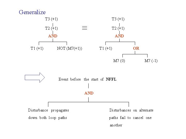
Generalize T 1 (+1) T 3 (+1) T 2 (+1) AND NOT (M 7(+1)) T 1 (+1) OR M 7 (0) M 7 (-1) Event before the start of NFFL AND Disturbance propagates Disturbances on alternate down both loop paths fail to cancel one another
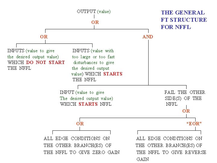
OUTPUT (value) THE GENERAL FT STRUCTURE FOR NFFL OR OR AND INPUTS (value to give the desired output value) WHICH DO NOT START THE NFFL INPUTS (value with too large or too fast disturbances to give the desired output value) WHICH STARTS THE NFFL INPUT (value to give The desired output value) WHICH STARTS NFFL OR ALL EDGE CONDITIONS ON THE OTHER BRANCH(ES) OF THE NFFL TO GIVE ZERO GAIN FAIL THE OTHER SIDE(S) OF THE NFFL OR “EOR” ALL EDGE CONDITIONS ON THE OTHER BRANCH(ES) OF THE NFFL TO GIVE REVERSE GAIN
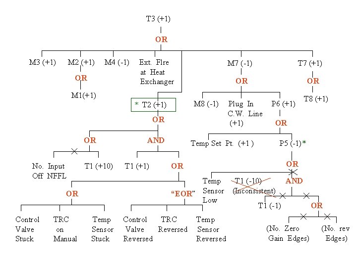
T 3 (+1) OR M 3 (+1) M 2 (+1) M 4 (-1) OR Ext. Flre at Heat Exchanger M 1(+1) M 7 (-1) OR M 8 (-1) * T 2 (+1) OR OR No. Input Off NFFL T 1 (+10) TRC on Manual T 1 (+1) Temp Sensor Stuck OR Plug In C. W. Line (+1) P 6 (+1) P 5 (-1)* OR OR Control TRC Valve Reversed T 8 (+1) OR Temp Set Pt. (+1 ) Temp “EOR” Sensor Low OR Control Valve Stuck AND T 7 (+1) Temp Sensor Reversed T 1 (-10) (Inconsistent) AND T 1 (-1) (No. Zero Gain Edges) OR (No. rev Edges)
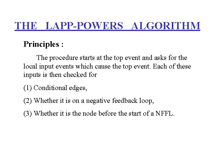
THE LAPP-POWERS ALGORITHM Principles : The procedure starts at the top event and asks for the local input events which cause the top event. Each of these inputs is then checked for (1) Conditional edges, (2) Whether it is on a negative feedback loop, (3) Whether it is the node before the start of a NFFL.

THE LAPP-POWERS FAULT TREE SYNTHESIS ALGORITHM The procedure discussed below is a systematic means for generating fault trees. Once the method is learned, it is possible to accurately and rapidly generate fault trees for a wide range of processes. When learning the method, keep several things in mind : 1. The definitions of feedback and feed orward loops are the keys to the method. Make sure you can find these loops in the process and digraph model. 2. The value of a process variable deviation (-10, -1, +10) is important to the fault tree development. Make sure you understand the definitions of these deviations and how feedback and feed forward loops behave when encountering variables with different ranges. 3. Take the input variables one at time and don’t jump ahead.
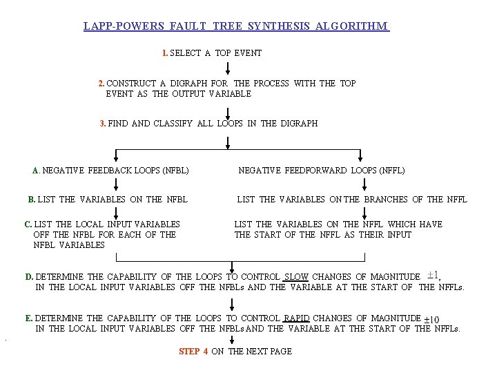
LAPP-POWERS FAULT TREE SYNTHESIS ALGORITHM 1. SELECT A TOP EVENT 2. CONSTRUCT A DIGRAPH FOR THE PROCESS WITH THE TOP EVENT AS THE OUTPUT VARIABLE 3. FIND AND CLASSIFY ALL LOOPS IN THE DIGRAPH A. NEGATIVE FEEDBACK LOOPS (NFBL) B. LIST THE VARIABLES ON THE NFBL C. LIST THE LOCAL INPUT VARIABLES OFF THE NFBL FOR EACH OF THE NFBL VARIABLES NEGATIVE FEEDFORWARD LOOPS (NFFL) LIST THE VARIABLES ON THE BRANCHES OF THE NFFL LIST THE VARIABLES ON THE NFFL WHICH HAVE THE START OF THE NFFL AS THEIR INPUT D. DETERMINE THE CAPABILITY OF THE LOOPS TO CONTROL SLOW CHANGES OF MAGNITUDE , IN THE LOCAL INPUT VARIABLES OFF THE NFBLs AND THE VARIABLE AT THE START OF THE NFFLs. . E. DETERMINE THE CAPABILITY OF THE LOOPS TO CONTROL RAPID CHANGES OF MAGNITUDE IN THE LOCAL INPUT VARIABLES OFF THE NFBLs AND THE VARIABLE AT THE START OF THE NFFLs. STEP 4 ON THE NEXT PAGE
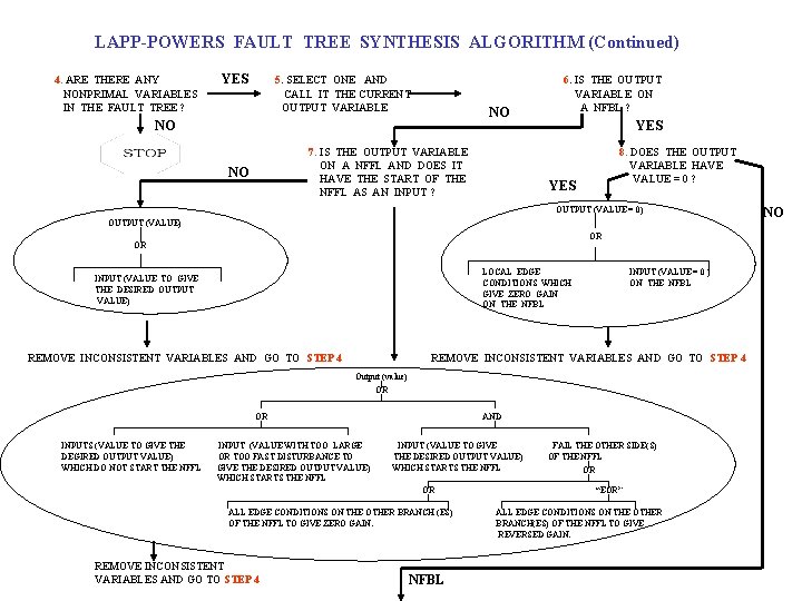
LAPP-POWERS FAULT TREE SYNTHESIS ALGORITHM (Continued) 4. ARE THERE ANY NONPRIMAL VARIABLES IN THE FAULT TREE ? YES 5. SELECT ONE AND CALL IT THE CURRENT OUTPUT VARIABLE NO NO 7. IS THE OUTPUT VARIABLE ON A NFFL AND DOES IT HAVE THE START OF THE NFFL AS AN INPUT ? NO 6. IS THE OUTPUT VARIABLE ON A NFBL ? YES 8. DOES THE OUTPUT VARIABLE HAVE VALUE = 0 ? YES OUTPUT (VALUE = 0) OUTPUT (VALUE) OR OR LOCAL EDGE CONDITIONS WHICH GIVE ZERO GAIN ON THE NFBL INPUT (VALUE TO GIVE THE DESIRED OUTPUT VALUE) REMOVE INCONSISTENT VARIABLES AND GO TO STEP 4 INPUT (VALUE = 0 ) ON THE NFBL REMOVE INCONSISTENT VARIABLES AND GO TO STEP 4 Output (value) OR OR INPUTS (VALUE TO GIVE THE DEGIRED OUTPUT VALUE) WHICH DO NOT START THE NFFL INPUT (VALUE WITH TOO LARGE OR TOO FAST DISTURBANCE TO GIVE THE DESIRED OUTPUT VALUE) WHICH STARTS THE NFFL AND INPUT (VALUE TO GIVE THE DESIRED OUTPUT VALUE) WHICH STARTS THE NFFL OR ALL EDGE CONDITIONS ON THE OTHER BRANCH (ES) OF THE NFFL TO GIVE ZERO GAIN. REMOVE INCONSISTENT VARIABLES AND GO TO STEP 4 NFBL FAIL THE OTHER SIDE(S) OF THE NFFL OR “EOR” ALL EDGE CONDITIONS ON THE OTHER BRANCH(ES) OF THE NFFL TO GIVE REVERSED GAIN. NO
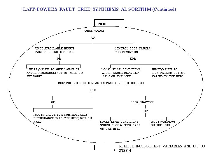
LAPP-POWERS FAULT TREE SYNTHESIS ALGORITHM (Continued) NFBL Output (VALUE) OR UNCONTROLLABLE INPUTS PASS THROUGH THE NFBL CONTROL LOOP CAUSES THE DEVIATION OR EOR INPUTS (VALUE TO GIVE LARGE OR FAST DISTURBANCE) NOT ON NFBL OR SET POINT LOCAL EDGE CONDITIONS WHICH CAUSE REVERSED GAIN ON THE NFBL INPUT (VALUE TO GIVE DESIRED OUTPUT VALUE) ON THE NFBL CONTROLLABLE DISTURBANCES PASS THROUGH THE NFBL AND OR LOOP INACTIVE OR INPUTS (VALUE FOR CONTROLLABLE DISTURBANCE INTO THE NFBL) NOT ON NFBL LOCAL EDGE CONDITIONS WHICH GIVE A ZERO GAIN ON THE NFBL INPUT (VALUE=0) ON THE NFBL REMOVE INCONSISTENT VARIABLES AND GO TO STEP 4
[EXAMPLE] HEAT EXCHANGER WITH TEMPERATURE FEEDBACK CONTROL The process shown in the next figure is used to cool nitric acid prior to mixing with benzene in a nitration reactor. The temperature of stream 8 is important. If it is too high (T 8 (+1)), the nitration becomes too fast and an explosion may occur.
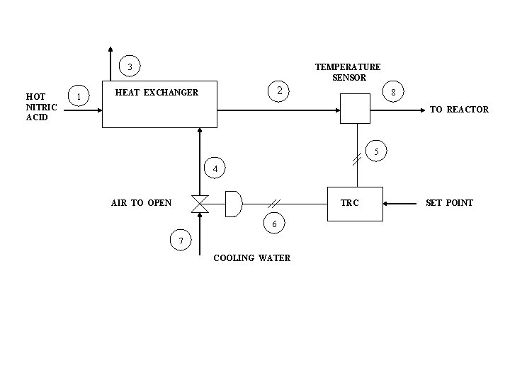
3 HOT NITRIC ACID 1 TEMPERATURE SENSOR 2 HEAT EXCHANGER 8 TO REACTOR 5 4 AIR TO OPEN TRC 6 7 COOLING WATER SET POINT
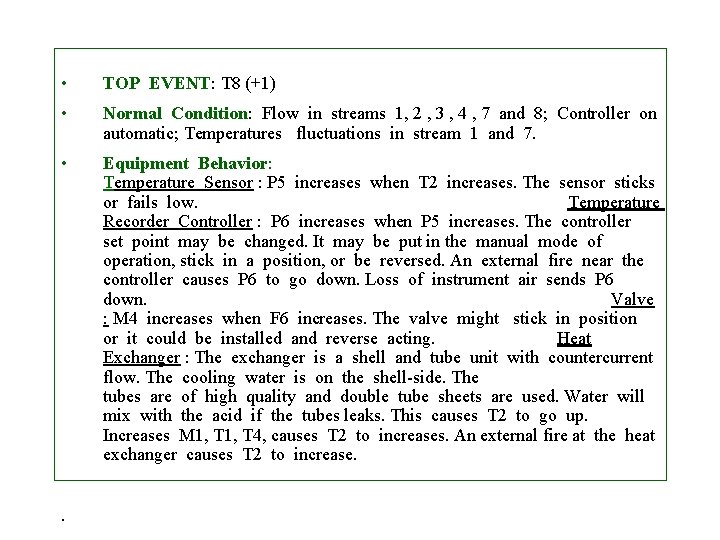
• TOP EVENT: T 8 (+1) • Normal Condition: Flow in streams 1, 2 , 3 , 4 , 7 and 8; Controller on automatic; Temperatures fluctuations in stream 1 and 7. • Equipment Behavior: Temperature Sensor : P 5 increases when T 2 increases. The sensor sticks or fails low. Temperature Recorder Controller : P 6 increases when P 5 increases. The controller set point may be changed. It may be put in the manual mode of operation, stick in a position, or be reversed. An external fire near the controller causes P 6 to go down. Loss of instrument air sends P 6 down. Valve : M 4 increases when F 6 increases. The valve might stick in position or it could be installed and reverse acting. Heat Exchanger : The exchanger is a shell and tube unit with countercurrent flow. The cooling water is on the shell-side. The tubes are of high quality and double tube sheets are used. Water will mix with the acid if the tubes leaks. This causes T 2 to go up. Increases M 1, T 4, causes T 2 to increases. An external fire at the heat exchanger causes T 2 to increase. .
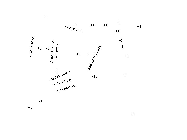
+1 +1 FOU +1 LED ) +1 +1 -1 0 ) CK TU RS SO 0 +1 EN +1 +1 C (TR -1 MP. S -1 ERS V E R ST (TRC ) ED -10 +1 ) UCK A NM 0 (O (TE +1 +1 (CONTROL V ALVE REVERSED) 0 VALVE STUCK 0 (HX -1 NUA L) -1 +1 +1
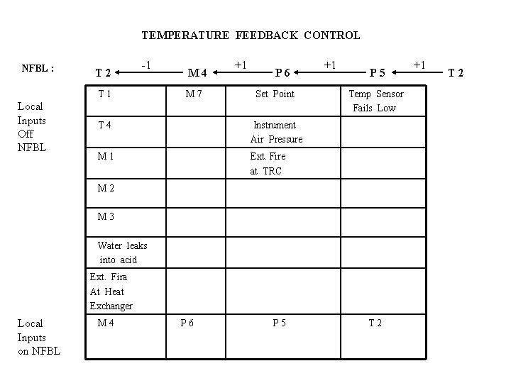
TEMPERATURE FEEDBACK CONTROL NFBL : T 2 -1 T 1 Local Inputs Off NFBL M 4 M 7 +1 P 6 Set Point T 4 Instrument Air Pressure M 1 Ext. Fire at TRC +1 P 5 Temp Sensor Fails Low M 2 M 3 Water leaks into acid Ext. Fira At Heat Exchanger Local Inputs on NFBL M 4 P 6 P 5 T 2 +1 T 2
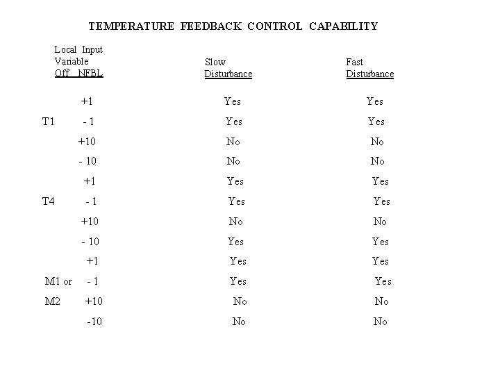
TEMPERATURE FEEDBACK CONTROL CAPABILITY Local Input Variable Off NFBL Slow Disturbance Fast Disturbance +1 Yes -1 Yes +10 No No - 10 No No +1 Yes -1 Yes +10 No No - 10 Yes +1 Yes M 1 or -1 Yes M 2 +10 No No -10 No No T 1 T 4
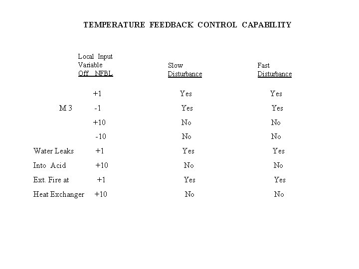
TEMPERATURE FEEDBACK CONTROL CAPABILITY Local Input Variable Off NFBL Slow Disturbance Fast Disturbance +1 Yes -1 Yes +10 No No -10 No No Water Leaks +1 Yes Into Acid +10 No No Ext. Fire at +1 Yes +10 No No M 3 Heat Exchanger
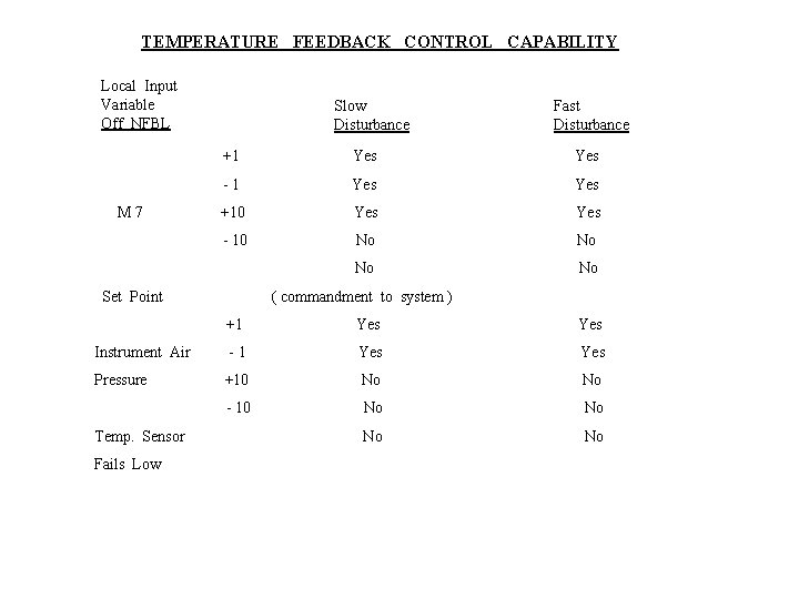
TEMPERATURE FEEDBACK CONTROL CAPABILITY Local Input Variable Off NFBL M 7 Slow Disturbance Fast Disturbance +1 Yes -1 Yes +10 Yes - 10 No No Set Point ( commandment to system ) +1 Yes Instrument Air -1 Yes Pressure +10 No No - 10 No No Temp. Sensor Fails Low
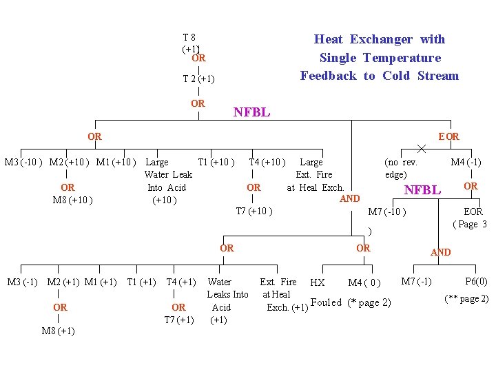
Heat Exchanger with Single Temperature Feedback to Cold Stream T 8 (+1) OR T 2 (+1) OR NFBL OR EOR M 3 (-10 ) M 2 (+10 ) M 1 (+10 ) Large T 1 (+10 ) Water Leak OR Into Acid M 8 (+10 ) T 4 (+10 ) OR T 7 (+10 ) Large Ext. Fire at Heal Exch. AND (no rev. edge) M 4 (-1) OR NFBL M 7 (-10 ) EOR ( Page 3 ) OR M 3 (-1) M 2 (+1) M 1 (+1) OR M 8 (+1) T 1 (+1) T 4 (+1) OR T 7 (+1) Water Leaks Into Acid (+1) OR Ext. Fire HX M 4 ( 0 ) at Heal Exch. (+1) Fouled (* page 2) AND M 7 (-1) P 6(0) (** page 2)
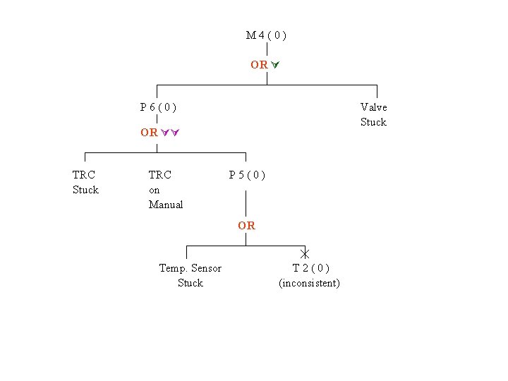
M 4(0) OR Valve Stuck P 6(0) OR TRC Stuck TRC on Manual P 5(0) OR Temp. Sensor Stuck T 2(0) (inconsistent)
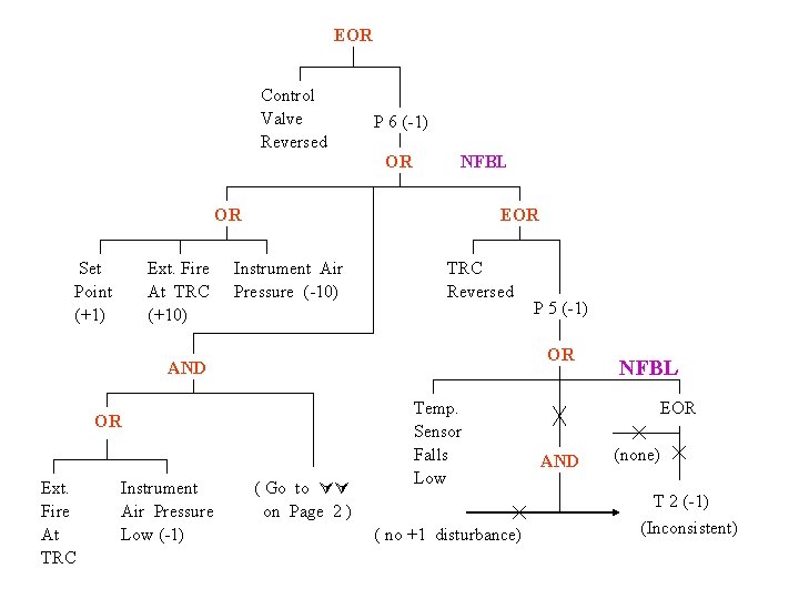
EOR Control Valve Reversed P 6 (-1) OR NFBL OR Set Point (+1) Ext. Fire At TRC (+10) EOR Instrument Air Pressure (-10) TRC Reversed OR AND OR Ext. Fire At TRC Instrument Air Pressure Low (-1) P 5 (-1) ( Go to on Page 2 ) Temp. Sensor Falls Low ( no +1 disturbance) NFBL EOR AND (none) T 2 (-1) (Inconsistent)
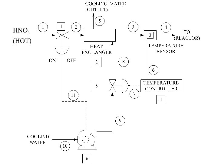
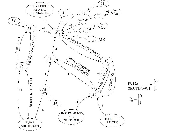
[ Example ] HEAT EXCHANGER WITH TEMPERATURE CONTROL LOOP AND PUMP SHUTDOWN SYSTEM The process here maintains the temperature of stream 4 in two ways. First, there is a negative feedback loop from the outlet temperature ( T 3 ) through the cooling water flow rate ( M 6 ). Second, a sensor on the pump will completely close the nitric acid feed valve if the pump shuts down.
M 8 PUMP SHUTDOWN
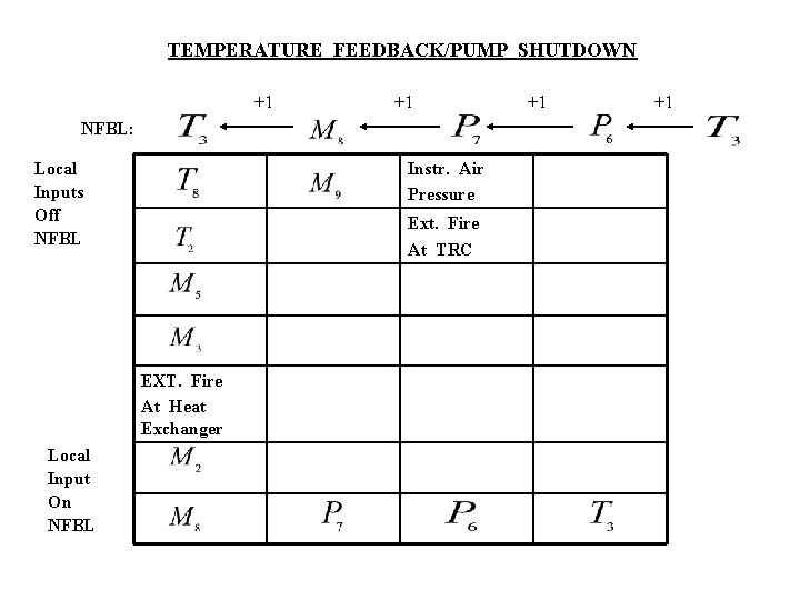
TEMPERATURE FEEDBACK/PUMP SHUTDOWN +1 +1 NFBL: Local Inputs Off NFBL Instr. Air Pressure Ext. Fire At TRC EXT. Fire At Heat Exchanger Local Input On NFBL +1 +1
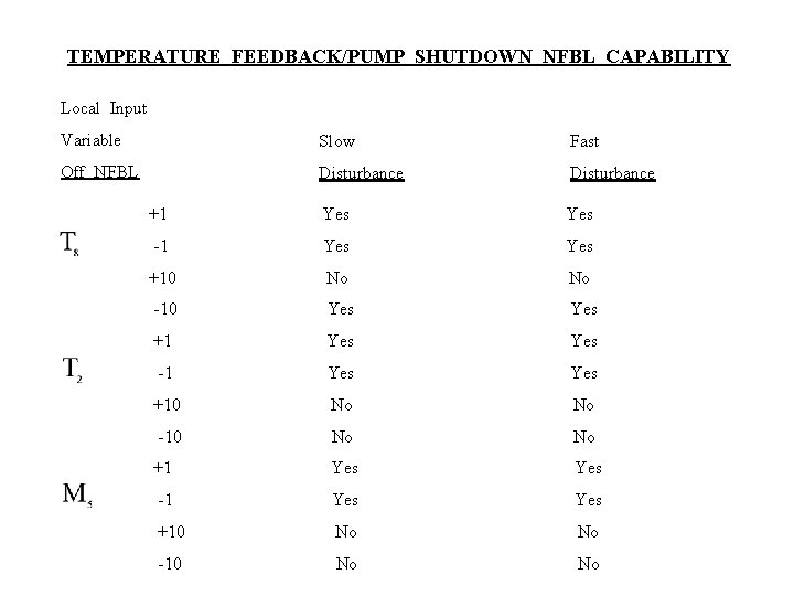
TEMPERATURE FEEDBACK/PUMP SHUTDOWN NFBL CAPABILITY Local Input Variable Slow Fast Off NFBL Disturbance +1 Yes -1 Yes +10 No No -10 Yes +1 Yes Yes -1 Yes Yes +10 No No -10 No No
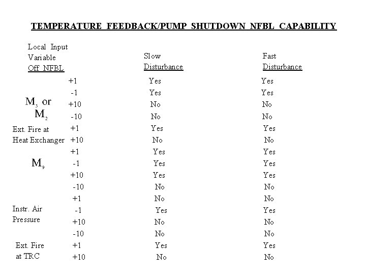
TEMPERATURE FEEDBACK/PUMP SHUTDOWN NFBL CAPABILITY Local Input Variable Off NFBL +1 -1 +10 -10 +1 Ext. Fire at Heat Exchanger +10 +1 -1 +10 -10 +1 Instr. Air -1 Pressure +10 -10 Ext. Fire +1 at TRC +10 Slow Disturbance Yes No No Yes No Fast Disturbance Yes No No Yes No
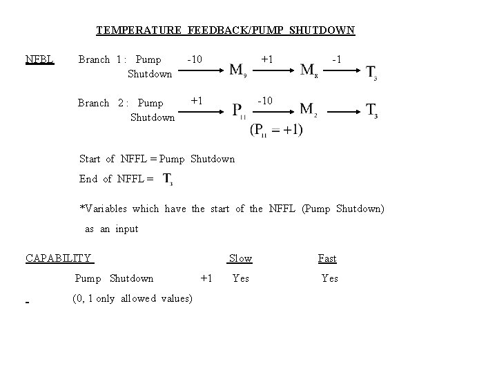
TEMPERATURE FEEDBACK/PUMP SHUTDOWN NFBL Branch 1 : Pump Shutdown -10 +1 Branch 2 : Pump Shutdown +1 -10 -1 Start of NFFL = Pump Shutdown End of NFFL = *Variables which have the start of the NFFL (Pump Shutdown) as an input CAPABILITY Pump Shutdown (0, 1 only allowed values) +1 Slow Fast Yes
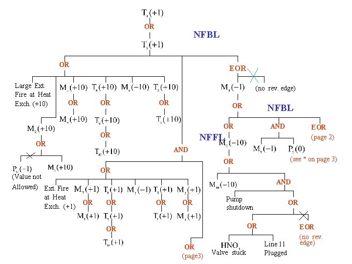
OR NFBL OR Large Ext. Fire at Heat Exch. (+10) EOR (no rev. edge) OR OR NFBL OR OR AND NFFL OR AND (see * on page 3) OR (Value not Allowed) Ext. Fire at Heat Exch. (+1) EOR (page 2) OR AND OR OR Pump shutdown OR OR (page 3) Valve stuck Line 11 Plugged EOR (no rev. edge)
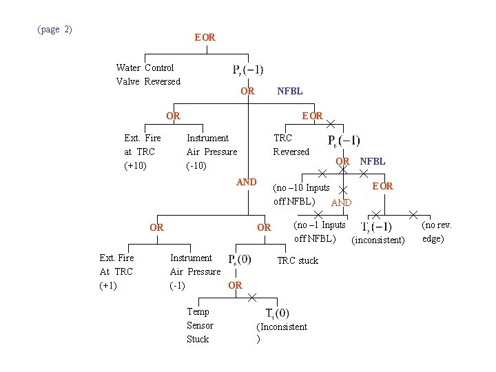
(page 2) EOR Water Control Valve Reversed OR NFBL OR Ext. Fire at TRC (+10) EOR Instrument Air Pressure (-10) TRC Reversed AND OR Ext. Fire At TRC (+1) OR Instrument Air Pressure OR (-1) Temp Sensor Stuck OR (no – 10 Inputs off NFBL) AND NFBL EOR (no – 1 Inputs off NFBL) (inconsistent) TRC stuck (Inconsistent ) (no rev. edge)
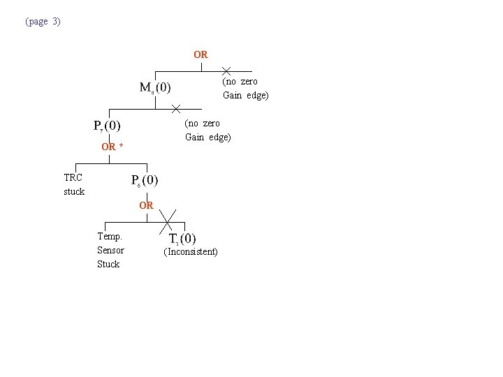
(page 3) OR (no zero Gain edge) OR * TRC stuck OR Temp. Sensor Stuck (Inconsistent)

[Example] A HEAT EXCHANGER WITH TEMPERRATURE FEEDBACK TO THE HOT FEED STREAM AND PUMP SHUTDOWN The outlet temperature of this process is on feedback control through the flow rate of hot nitric acid. A pump shutdown closes valve v 2. Using the digraph given on Figure 8, construct a fault tree for the event too high.
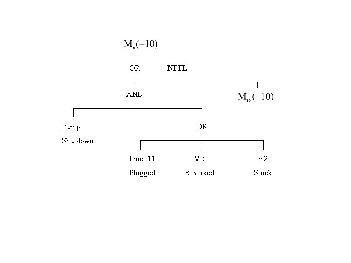
OR NFFL AND Pump OR Shutdown Line 11 V 2 Plugged Reversed Stuck
- Slides: 38