Fatigue to Failure FEA Predictions of Limit Conditions


![Expanded Diameter Expansion Recoil Ideal ID Expansion [mm] 2. 926 Maximum OD [mm] 3.](https://slidetodoc.com/presentation_image/195fe8cd0d0c71bec54247e8a8d9813b/image-4.jpg "Expanded Diameter Expansion Recoil Ideal ID Expansion [mm] 2. 926 Maximum OD [mm] 3.")


- Slides: 9
Fatigue to Failure: FEA Predictions of Limit Conditions for Axial Fatigue Loading of Generic Coronary Stent Designs Part 2: Geometry 1 with EP correction Prepared for ASTM F 04. 30. 06 May, 2007
Dimensional Correction 0. 085 mm 0. 11 mm
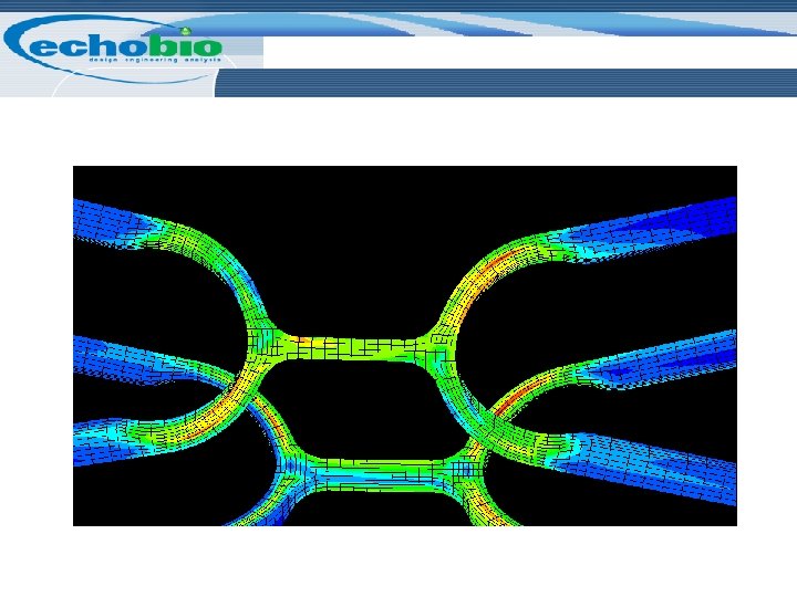
Expansion Analysis Stress at max expansion Stress after recoil Plastic strain due to expansion
Expanded Diameter Expansion Recoil Ideal ID Expansion [mm] 2. 926 Maximum OD [mm] 3. 34 3. 19 Minimum ID [mm] 2. 9 2. 75 Minimum ID Maximum OD Expansion Recoil
Location of Max Mean and Alternating Stress Mean Stress Alternating Stress
Effect of Residual Stress Effective stress during extension with residual expansion stress Case Extension Max Stress Effective stress during extension without residual expansion stress Comments Residual Stress ± 0. 33% 364 MPa -Large tensile and compressive stresses in the middle of struts and bridges -Yield stress increased due to load history No Residual Stress ± 0. 33% 110 MPa -Uniform load path with unaltered yield stress
Fatigue Scenario Studies Case Stress State Strain State Fatigue Condition Mean Stress Alternating Stress Expanded Residual Stress ~300 MPa Cold Work ~4. 8% ± 0. 33% 243 MPa 121 MPa Expanded Residual Stress ~300 MPa Cold Work ~4. 8% ± 0. 27% 243 MPa 98 MPa Expanded (annealed) No Residual Stress No Cold Work ± 0. 33% 0 MPa 110 MPa
Fatigue Analysis ±. 70 % is roughly Here ±. 50 % is roughly Here ±. 33 % is Here ±. 33 % without residual stress is Here