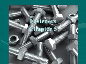
FASTENERS AND ANCHORS CONTREN Series 40103 07 1


- Slides: 61

FASTENERS AND ANCHORS CONTREN Series # 40103 -07

1. 0. 0 Introduction • Industry used a multitude of types of fasteners to assemble and install equipment, parts, and materials. • Industrial Maintenance personnel must be familiar with the different types of fasteners and their applications.

2. 0. 0 Threaded Fasteners • Most commonly used fastener. • Uses threads to hold parts together. • Terminology includes: – Nuts – Bolts – Screws

2. 1. 0 Thread Standards • Threads are manufactured to industryestablished standards for uniformity. • Unified Standard (American Standard) – The most common thread standard. – Establishes thread series and thread classes.

2. 1. 1 Thread Series • Groups threads by pitch (threads per inch). • UNC – Unified National Coarse – General-purpose use • UNF – Unified National Fine – Finer threads for a tighter fit • UNEF – Unified National Extra Fine – For thin-wall tubes, nuts, ferrules, and couplings

2. 1. 2 Thread Classes • Groups threads by the degree of tolerance permitted. • Class A is for external threads (bolts) • Class B is for internal threads (nuts)

2. 1. 2 Thread Classes • Class 1 A – loose fitting bolt threads – Used for quick and easy threading – Used in areas with high contamination – Maximum clearance on bolt threads • Class 2 A – bolt threads with nominal clearance – Most commonly used thread class for bolts • Class 3 A – tight fitting bolt threads – Used when precision fit is required – Threads must be very clean – Minimum clearance on bolt threads

2. 1. 2 Thread Classes • Class 1 B – loose fitting nut threads – Used for quick and easy threading – Used in areas with high contamination – Maximum clearance on nut threads • Class 2 B – nut threads with nominal clearance – Most commonly used thread class for nuts • Class 3 B – tight fitting nut threads – Used when precision fit is required – Threads must be very clean – Minimum clearance on nut threads

2. 1. 3 Thread Identification ¾ - 10 UNC – 2 A - LH 1. 2. 3. 4. 5. Nominal size (1) (2) (3) (4) (5) – Approximate diameter of fastener ( fractional) TPI - Threads per Inch (Pitch) – Each nominal diameter has a standard number of threads per inch per series Thread Series Symbol – Indicates the unified standard thread series – (UNC, UNF, UNEF) Thread Class Symbol – Indicates the closeness of fit between the bolt threads (1 A, 2 A, 3 A) and the nut threads (1 B, 2 B, 3 B) Left Hand Thread Symbol – Used ONLY if threads are left-handed

2. 1. 4 Thread Design • Unified Standard Threads – Standard thread design for most all common bolts and nuts – Used primarily to hold parts together

2. 1. 4 Thread Design • Power Transmission Threads – Used to move machine parts for the purpose of adjusting, setting, or transmitting power. – Not typically used to hold parts together. • The following three thread designs are the most common Power Transmission Threads

2. 1. 4 Thread Design • Buttress Threads – One side of thread is cut square, the other side has a slant – Great strength along thread axis in one direction only – Used extensively to screw thin tubular parts together

2. 1. 4 Thread Design • Square Threads – Strongest thread – Threads have parallel sides – Hard to machine

2. 1. 4 Thread Design • Acme Threads • Easier to machine than the square thread • Almost as strong as the square thread

2. 1. 5 Grade Markings • Markings on the head of the bolt to signify the quality of the bolt. • SAE (Society of Automotive Engineers) • ASTM (American Society for Testing and Materials International) – Established these standards • The greater the number of marks, the higher the quality of the bolt.

2. 1. 5 Grade Markings No Marks SAE Grade 1 SAE Grade 2 ASTM A 307 Low Carbon 74, 000 psi 5 Marks SAE Grade 7 Medium Carbon Quenched & Tempered 133, 000 psi 9 4 A 4 3 Marks SAE Grade 5 ASTM A 449 Medium Carbon Tempered 120, 000 psi 6 Marks SAE Grade 8 ASTM A 354 Medium Carbon Quenched & Tempered 150, 000 psi

2. 2. 0 Bolt and Screw Types • Made in a variety of shapes • Made from a variety of materials • Identified by the head type

2. 2. 1 Machine Screws • Used for general assembly • Size range from very small to ½” diameter Pozidriv Phillips Torx Hex (Allen) Slotted Clutch Robertson

2. 2. 1 Machine Screws • Head designations PAN HEAD FILLISTER HEAD FLAT HEAD TRUSS HEAD OVAL HEAD ROUND HEAD

2. 2. 2 Machine Bolts • Used for assembly where close tolerances are not required. • Size range from ¼” to 3”. • Normally have a square (4 sides) or hexagonal (6 sides) head.

2. 2. 3 Cap Screws • Used on high-quality assemblies where a finished appearance is required

2. 2. 4 Setscrews • Made of heat-treated steel • Used to lock pulleys and gears on shafts to prevent slipping Flat (Half-Dog) Cone Cup Oval Knurled Full (Full-Dog)

2. 2. 5 Stud Bolts • Threaded on both ends • Screwed into a tapped hole in the back part with a nut on the other end holding the front part tight against the back part • Thread Rod is a type that is threaded along the full length of the stud

2. 3. 0 Nuts • Different configurations for different applications • Usually, most are hexagonal or square coupling nut regular hex nut regular square nut flange nut

2. 3. 1 Jam Nut • Used to lock a standard nut in place on a bolt or stud bolt • Typically, about half the height of a regular nut jam nut regular hex nut

2. 3. 2 Castellated, Slotted, and Self-Locking Nuts • Used in critical applications where the nut cannot be allowed to loosen bolt cuts threads in the nylon insert nylon locking nut cotter pin placed through slot and hole in bolt slotted nut deformation causes thread interference cotter pin placed through slot and hole in bolt self-locking nut castle nut

2. 3. 3 Acorn Nuts • Used when appearance is important • Used when safety is important by covering the sharp threads on the end of the bolt or stud cap (acorn) nut

2. 3. 4 Wing Nut • Used for rapid tightening and loosening by hand only wing nut

2. 4. 0 Washers • Fits under the bolt head or nut • Used to enlarge the area of force onto the work piece • Lock washers also prohibits loosening of the bolt or nut

2. 4. 1 Lock Washers • Designed to keep the bolt or nut from working loose External (Greatest Resistance) Internal Split-Ring Ribbed Internal - External Countersunk

2. 4. 2 Flat and Fender Washers • Flat washer spreads the load over a larger area • Fender Washers forms a bridge over a large hole Flat Washer Wedge Washer -for angled surface Fender Washer -for oversized holes Shoulder Washer -for insulation Cone Washer -for appearance Wave Washer -for preloading

2. 5. 0 Installing Threaded Fasteners • Assure proper hole size for the type of bolt • Torque bolt and nut to correct setting • Use safety wire or cotter pin, if required • Most important, use correct grade of bolt

3. 0. 0 Non-Threaded Fasteners • There are many other fastening devices that are not threaded • • • Retainers Pins Clamps Rivets Tie Wraps

3. 1. 0 Retainer Fasteners • Internal and external holding Non-Groove Fasteners Internal Retaining Ring Spiral Ring External Retaining Ring E Ring Internal Self-Locking Ring External Self-Locking Ring

3. 2. 0 Keys • A keyway slot is cut in the shaft and the component to be locked to it. • A key is inserted into the keyway Square Key Gib Head Key Woodruff Key (Semi-Circular) Pratt & Whitney Key

3. 3. 0 Pin Fasteners • Long, circular fasteners • • Dowel Pins Taper Pins Spring Pins Cotter Pins

3. 3. 1 Dowel Pins • Precise positioning of mating parts • Grooved pins have a higher holding capability due to spring action of the grooves

3. 3. 2 Taper and Spring Pins • Normally used to lock gears, pulleys, etc onto a shaft • The taper allows for a tight “wedge” fit • Spring (Roll) pins compress into the hole, creating a very tight fit Taper Pin Spring Pin

3. 3. 3 Cotter Pins • Usually inserted through a hole drilled crosswise through the shaft • Used to keep components from falling off the shaft Cotter Pin Shaft Lock Hitch Pin Pull Loop Spread ends apart to keep cotter pin from backing out

3. 4. 0 Blind / Pop Rivets • Ideal fastener for fastening when only one side of the joint can be reached.

3. 5. 0 Tie Wraps • Self-locking strap (usually nylon) to fasten bundles of cables or wires together

4. 0. 0 Special Fasteners • Threaded fasteners designed for a specific application. • Eye Bolts • Thread Inserts • Panel and Electrical Mounts

4. 1. 0 Eye Bolts • Has a loop (eye) on one end for attaching lifting cables or for cable or wire guides Swivel Eye Bolt Plain Eye Bolt Shoulder Eye Bolt

4. 2. 0 Thread Inserts • Provides high strength threads in soft material • Replaces damaged or stripped threads in tapped holes Heli-Coil Thread Inserts E-Z Lock Thread Inserts This end goes in first. Insertion tool grips this prong.

4. 3. 0 Panel and Electrical Mounts • Stamped from sheet metal • Clips to panels for attaching components J-nut G-nut regular nut attached U-nut Cage Nut Regular nut caged in a spring clip

5. 0. 0 Mechanical Anchors • Used to attach components to a material that cannot tapped or the back side is unreachable • • One-Step Anchors Bolt Anchors Screw Anchors Self-Drilling Anchors

5. 1. 0 One-Step Anchors • Driven through the component to be anchored and the hole in the substrate at the same time • • • Wedge Anchors Stud Bolt Anchors Sleeve Anchors One-Piece Anchors Hammer-Set Anchors Threaded Rod Anchors

5. 1. 1 Wedge Anchors • Comes with a wedge on the bottom and a nut and washer on the top • Anchor is driven through the component hole into the substrate hole and tightened with the nut

5. 1. 2 Stud Bolt Anchors • Depth of hole is critical • Threaded wedge is driven down onto the taper to lock it into place

5. 1. 3 Sleeve Anchors • Comes with a wedge along the length of the anchor and a nut and washer on the top • Anchor is driven through the component hole into the substrate hole and tightened with the nut

5. 1. 4 One-Piece (Split) Anchors • Drive in with no further tightening • Flex in the split locks the anchor in place

5. 1. 5 Hammer-Set Anchors • Pushed into a hole, then nail is driven in to lock the anchor in place • Comes with or without a final tightening nut

5. 1. 6 Threaded Rod Anchors • Pushed into a hole • Threading a thread rod expands the housing to lock the anchor in place

5. 2. 0 Bolt Anchors • Installed flush with the surface of the substrate • The component is then anchored with machine bolts • • Drop-In Anchors Single Expansion Anchors Double Expansion Anchors Caulk-In Anchors

5. 2. 1 Drop-In Anchors • Works much like a wedge anchor

5. 2. 2 Single- and Double-Expansion Anchors • Works much like a sleeve anchor • Double expansion anchors are the best choice with the strength of the substrate is questionable Double Single

5. 2. 3 Lead (Caulk-In) Anchors • Must be driven down with the setting tool to lock the anchor in place

5. 3. 0 Screw Anchors • Threaded directly into the substrate

5. 4. 0 Self-Drilling Anchors • Drills its own hole and locks itself in place Dywidag

5. 5. 0 Guidelines For Drilling Anchor Holes • Check specifications for proper hole diameter and depth • Check condition of hammer drill and work area • Observe all safety precautions

6. 0. 0 Epoxy Anchoring • Hole is drilled to accept a j-bolt • J-bolt is secured in place by a wood or metal frame • Epoxy is poured into the hole, anchoring the j-bolt
 Lifting device
 Stores minerals and anchors muscles
 Types of career anchors
 Types of career anchors
 Aircraft tie down procedures
 Behavioral anchors for competencies
 Pci anchor
 Anchors away play
 Fasteners gaskets seals and sealants
 Building materials fasteners and adhesives
 Automotive fasteners gaskets and sealants
 Fastening
 Non threaded bolts
 Schraube fasteners turkey inc
 Axially loaded members
 Types of threaded fasteners
 Fasteners locking devices
 Manufacturer for wood joint fasteners
 Flexco bolt solid plate fasteners
 Types of mechanical fasteners
 Cylindrical snap fit
 Fasteners
 Examples of fasteners in sewing
 Subsea fasteners
 Chapter 15 using fasteners
 What is the life cycle of a snow leopard
 Bolt manufacturing process ppt
 Bossard fasteners catalogue pdf
 Series aiding and series opposing
 Maclaurin series vs taylor series
 Balmer series lyman series
 Taylor series of composite function
 Taylor series lesson
 Ibm p series vs i series
 Series-series feedback amplifier
 Arithmetic series formula
 Parallel circuit
 Arithmetic and geometric sequences and series
 10-2 arithmetic sequences and series
 The sum of geometric sequence
 Unit 10 sequences and series
 Series coil and multi-turn coil
 Series de fourier
 Chapter 12 sequences and series answers
 Sequence and series
 10-3 geometric sequences and series
 Reliability of series and parallel systems example
 Module 12 sequences and series
 Recursive formula geometric
 10-2 practice arithmetic sequences and series
 10-1 sequences series and sigma notation
 Differences between series and parallel circuits
 What is gymnastics?
 It is the sum of the terms of a geometric sequence. *
 Series circuit questions
 Occupational health and safety assessment series
 Short circuit series
 Capacitors in series formula
 Parallel circuit characteristics
 Current in series
 Chapter 23 series and parallel circuits
 Parallel resonance
