Fans Compressors and Turbines EGR 4347 Analysis and

Fans, Compressors, and Turbines EGR 4347 Analysis and Design of Propulsion systems

General Electric CF 6 -50

CFM-56

F 100 -PW-220 Turbofan Engine

F-404 vs. J 79

GP 7200 – GE and P&W For Airbus 380

Bird Strikes

Results

Results

Results

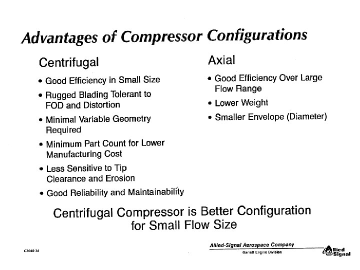
Compressors • AXIAL • CENTRIFUGAL

Axial Compressor

Complex Flow in Compressors General Electric

http: //www. pr. afrl. af. mil/divisions/prt/ihptet/brochure/Fans. Com. htm JTAGG III Advanced Concept Centrifugal Impeller with independent inducer and exducer will provide higher pressure ratio and efficiency. Integrating Forward Sweep and Splitter Technology are key features to achieving high efficiency and high JTDE Forward Swept Fan Blisk will be the first large pressure ratio. This stage will be forward swept rotor to be tested utilized as the JTAGG III low in a demonstrator engine. pressure compressor. The compression systems of tomorrow's aircraft gas turbine engines must have reduced weight, provide higher performance, and be more robust in order to develop pressures of up to seventy atmospheres to meet IHPTET Phase III goals. Significant progress has already been achieved through the application of advanced Computational Fluid Dynamics (CFD) analysis tools, innovative aerodynamic and mechanical design schemes, and high specific strength material systems. Aerodynamic sweep and "splittered" rotor designs provide higher pressure ratios and efficiencies with a significant improvement in stability margin. A Phase III two stage fan combined with a four stage compressor will provide the same performance as the three stage fan and ten stage compressor in the F 100 engine, dramatically reducing the number of parts while meeting Phase III production and maintenance cost goals. Hollow fan blades and organic and metal matrix composite rotating and static structures significantly reduce weight. The core A Forged Orthorhombic driven fan enables the variable cycle engine to operate as a turbofan or turbojet, vastly Transformed Super Alpha-2 broadening operational capability. Rotor and stator airfoil designs, analyzed with advanced Billet will be bonded to unsteady aerodynamic analysis codes, reduce aeromechanical design iterations which reduce Gamma Ti. Al to form a novel, design costs while increasing correctness. Numerous compression system designs have been dual alloy impeller. tested analyzed at the Air Force Research Laboratory's Compressor Research Facility (CRF) http: //www. pr. afrl. af. mil/divisions/prt/ihp and Compressor Aero Research Lab (CARL). tet/brochure/Materials. htm This 4 -stage ATEGG Compressor Rig, the highest loaded compressor ever built with acceptable stall margin and efficiency characteristics, meets the Phase III stage loading goals.

TURBINES • PURPOSE: Convert KE into shaft HP • ENVIRONMENT: – Favorable Pressure Gradient • more turning, more work per stage relative to compressor – Temps exceed material limits; cooling req’d – High stresses due to temp and rotation – Fixed geometry – 3/4 of energy available after combustor used to drive compressor

Parameters Affecting Turbine Blade Design Vibration Environment Tip Shroud Number of Blades Airfoil Shape Inlet Temperature Blade Cooling Material Trailing-Edge Thickness Allowable Stress Levels (AN 2) (N = Speed, RPM) Service Life Requirements

TURBINE ANALYSIS - Velocity Triangles

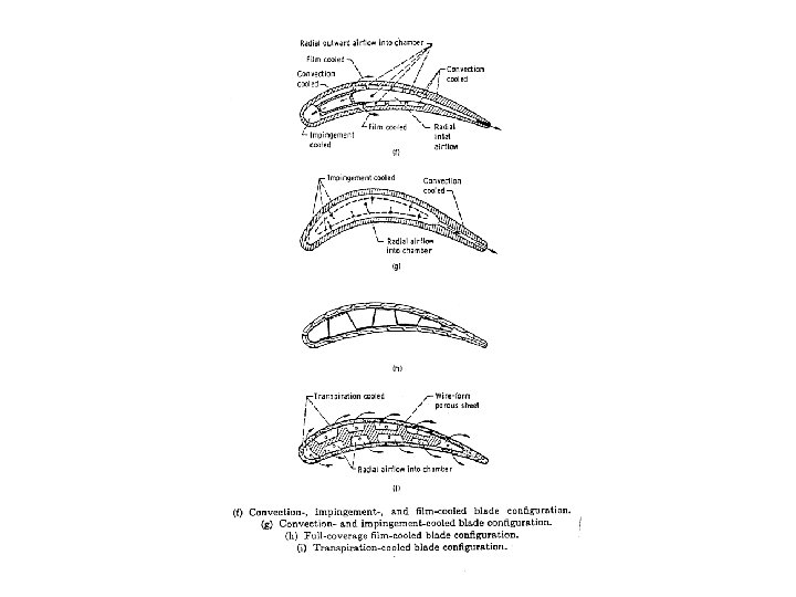
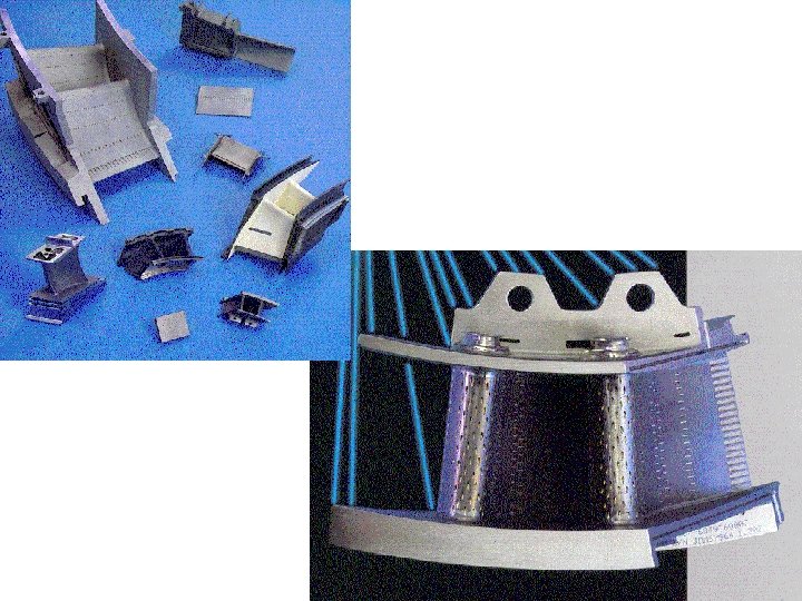
TURBINE COOLING • WHY? • TYPES OF DESIGNS • EFFECTIVENESS • THERMAL BARRIER COATING

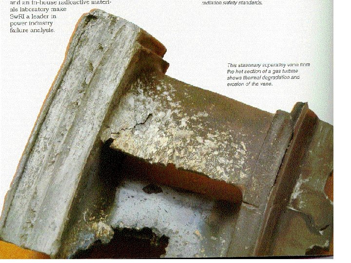
WHY? • Combustor gas temps exceed metal melting temps • To increase thrust-to-weight, temps increase faster than material capability • High metal temps weaken blade/reduce life • Cooling air can be distributed to reduce large temperature gradients (reduces thermal fatigue) - if not done properly, the reverse can happen

TURBINE COOLING

TURBINE COOLING

http: //www. pr. afrl. af. mil/divisions/prt/ihptet/brochure/Turbines. htm Castcool® High and Low Pressure Turbine Blades for ATEGG and JTDE will demonstrate capability at conditions more than 100°F above the Phase II turbine temperature objective. Improved Thermal Barrier Coatings which have reduced conductivity and weight will enable this turbine blade to meet Phase II and III turbine temperature goals. High Work Turbine Design demonstrates Phase II performance and cooling technology in rig and JTAGG I engine testing using advanced aerodynamics and cooling schemes in diffusion bonded airfoils. Modern turbines must maintain a balance between high performance, affordability, and design robustness in order to maximize engine payoff. Achieving production part cost, along with substantially improved life-cycle costs, requires development of significantly enhanced manufacturing techniques; strong, low density, affordable materials; and the use of concurrent engineering practices from initial design concept to "fielding" of the part. Development for component robustness and a need for long intervals between inspections and overhauls require parts with improved fatigue behavior. High performance cooling technologies will maximize the effectiveness of reduced cooling flows while improving life through the application of novel structural designs. Special emphasis is placed on enhanced analysis techniques, including 3 -D time accurate computational codes, to provide better understanding of the aerodynamic and heat transfer mechanisms occurring in extremely complex airfoils. Using the Air Force Research Laboratory 's Turbine Research Facility (TRF), advanced, short duration test methods are being applied to validate turbine aerodynamic and cooling designs. These test methods will be extended to measure turbine structural dynamics and high cycle fatigue characteristics.
- Slides: 33