FALSEWORK CODAL PROVISIONS Design of centering and shuttering


 False work shall")
 Loads on falsework are any")
 • falsework structure,")
 • Actual load")
 • Loads during")
 • Allowance shall")
")
 These loads include:")
 • Wind loads")
 • Permissible stresses shall not exceed")


 The total calculated deflection")
 • The formwork shall be designed to")
 • The acceptable")
")


 1 Shift from alignment +")
 9 Thickness of footings +")


")


- Slides: 76
FALSEWORK CODAL PROVISIONS Design of centering and shuttering
Is Falsework really important? • contractor is responsible for quality of Product • Why should we bother about formwork • We should be bothered about finish only v Is concentration on the end product the right approach? ?
We own the structure We are responsible for the finish So, why is it important? We are responsible for the functionality We are responsible for the safety Ø But we never study formwork/falsework Ø It is not treated a subject at all
Formwork? “A structure, usually temporary, but in some cases wholly or partly permanent, used to contain fresh concrete to mould it to the required shape and dimensions and to support it until it is able to support itself without prejudicing the final structure. It includes the surface in contact as with concrete as well as all necessary supports”
Temporary Structures • Materials, methods and techniques associated with temporary structures are: ü concrete formwork construction ü falsework/shoring ü scaffolding ü cofferdams ü earth-retaining structures ü construction dewatering.
Objectives of Falsework • Forms mould the concrete to desired size and shape and control its position and alignment. • But Falsework is more than a mould; it is a temporary structure that supports: ü its own weight + ü the freshly placed concrete + ü construction live loads (including materials, equipment, and personnel).
Objectives of Falsework • Basic objectives are: ü Quality - In terms of correct dimensions, rigidity for permissible deflection & tolerance limits, and strength. ü Safety - for both workmen and structure. ü Economy - the least consistent with quality and safety requirements. It is one of main concerns ü Efficient – Can be handled, erected and dismantled easily and used repeatedly. • Cooperation and coordination between engineer / architect and the contractor are necessary to achieve these goals.
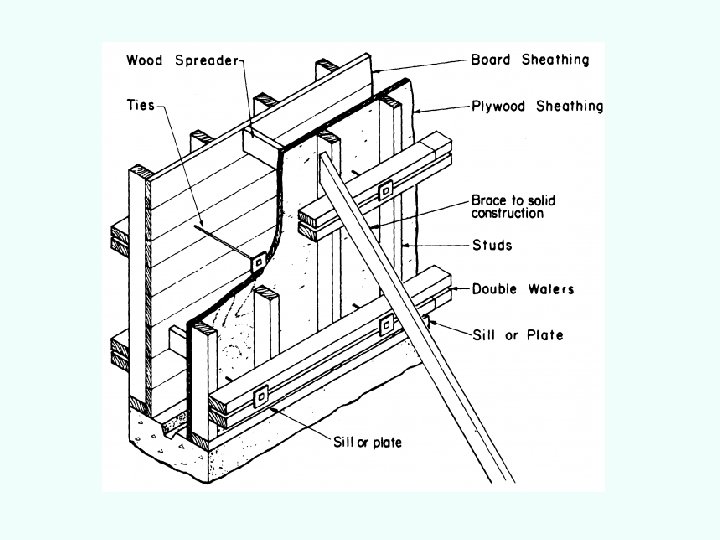
Form Materials and Accessories Typical wall form with components identified. Plywood sheathing is more common than board sheathing material.
Falsework Materials • Timber and Timber products like Plywood
Falsework Materials • Steel
Falsework Materials n n In 1908 the use of wood versus steel formwork was debated at the ACI convention. Also, the advantages of modular panel forming with its own connecting hardware, and good for extensive reuse were realized. By 1910 steel forms for paving were being produced commercially and used in the field. A 1909 construction scene shows the first application of steel forms for street paving.
Falsework Materials • Aluminum – Modular Formwork
Falsework Materials • Fiber Reinforced Plastics • Permanent Formwork of concrete etc.
Falsework Materials
Falsework Materials
Falsework Materials
FALSEWORK – CODAL PROVISIONS • Specification booklet of the Railways • Concrete Bridge Code • BIS codes: IS 14687(1999)- ‘False work for Concrete structures-Guidelines’ • ACI 347 -Guide to Formwork for Concrete • IRC-87: Guidelines formwork, falsework and temporary structures
BIS Codes formwork 1. IS 456 – 2000 Plain and reinforced concrete – code of practice 2. IS 14687 – 1999 Guidelines on false work for concrete structures 3. IS 883 Timber formwork 4. IS 4990 – 1993 Amd. No. 5 - 2006 Plywood for concrete shuttering work - specification 5. IS 2750 – 1964 Amd. No. 3 - 1980 Specifications for steel scaffolding 6. IS 4014 (Pt. I) – 1967 Reafmd. 2006 Code of Practice for Steel Tubular Scaffolding – Part I Definition and Materials 7. IS 4014 (Pt. II) – 1967 Reafmd. 2005 Code of Practice for Steel Tubular Scaffolding – Part II Safety regulations for scaffolding 8. IS 1161 – Steel forming and bracing 9. IS 3696 (Pt. 1) – 1987 Reafmd. 2002 Safety Codes for scaffolds and ladders – Part 1 Sacffolds 10. IS 3696 (Pt. 1) – 1987 Reafmd. 2002 Safety Codes for scaffolds and ladders – Part 2 Ladders 11 IS 3337 Code for Ballies for scaffolding work
Design of Falsework shall be designed • to meet the requirements of the permanent structure using relevant Indian Standards • should take into account the conditions of materials to be actually used for the falsework, environment and site consideration. • Should be checked for safety, overturning, overall stability and progressive collapse. • shall preferably be so designed that the vertical members are subjected to compressive force only under the action of combined horizontal and vertical loads. • should also take into account the sequence of concreting, specially in construction of cantilevers, domes, etc.
Design information Before proceeding to the design, • all the relevant design information should be obtained from the relevant sources. • The design information includes ü the site investigation report, ü Expected loading scheme of load transfer, ü sequence of erection and releasing, ü procedure of concreting and time frame.
LOADS for Design (Clause 6. 1. 2. of Concrete Bridge Code) False work shall be designed to cater following loads • Dead load of wet concrete and reinforcement • Weight of form work • Plant and equipment including impact • Impact due to deposition of concrete • Construction personnel • Pre-stressing loads • Lateral loads • Wind loads • Force due to water current, if any.
LOADS on FALSEWORK (Clause 7. 3 of IS 14687) Loads on falsework are any combinations of the following: • Dead loads, • Imposed loads, • Environmental loads, • Incidental loads during erection and operation, • Lateral pressure.
DEAD LOADS on FALSEWORK (Clause 7. 3. 1 of IS 14687) • falsework structure, self weight of formwork and any ancillary temporary work connected or supported by formwork, and • weight of freshly placed concrete directly supported by the formwork; (self load shall be determined either by actual measurement or in accordance with IS 875 (Part 1). • The unit weight of wet concrete including reinforcement shall be taken as 26 k. N/m 2. • Additional weights of fittings shall be included in the self weight calculation.
DEAD LOADS on FALSEWORK (Clause 7. 3. 1 of IS 14687) • Actual load of formwork shall be evaluated for use in design. • However, in absence of the data, load may be assumed as 500 N/m 2 for the purpose of initial calculations.
Imposed Loads on FALSEWORK (Clause 7. 3. 2 of IS 14687) • Loads during constructional operation shall constitute the imposed loads [see IS 875 ( Part 2 )]. • Loads due to construction personal, plant and equipments, vibration and impact of machine delivered concrete, lateral pressure of fresh concrete, unsymmetrical placement of concrete, concentrated load and storage of construction materials. • Imposition of any construction load on the partially constructed structures shall not be allowed unless specified in the drawings or approved by the engineer-in -charge.
Imposed Loads on FALSEWORK (Clause 7. 3. 2 of IS 14687) • Allowance shall be made in the falsework design to accommodate force or deformation in the post tensioned members.
Lateral Pressure due to fresh concrete (Clause 7. 3. 2. 4 of IS 14687) The factors affecting lateral pressure on forms are: • Density of concrete • Rate of placing • Vibrating • Temperature of concrete • Concrete Slump • Method of discharge and compaction • Width, depth & shape of section • Vertical form height • Constituent material of concrete like admixtures, aggregate, cementitious material
Environmental Loads on FALSEWORK (Clause 7. 3. 3 of IS 14687) These loads include: • Wind or seismic loads, • Earth pressure, • Water pressure, • Snow loads or ice loads, and • Thermal load, etc.
Environmental Loads on FALSEWORK (Clause 7. 3. 3 of IS 14687) • Wind loads should be taken in accordance with IS 875 (Part 3 ) subject to a minimum horizontal load equal to 3 percent of the vertical loads at critical level. • Earth pressure can occur on falsework as in the case of retaining walls. The rise in the water table may increase pressure on the falsework. • Shrinkage and early thermal movements in the freshly placed concrete should be assessed and accommodated in the design of formwork.
Permissible Stresses (Clause 7. 4 of IS 14687) • Permissible stresses shall not exceed the values specified in the relevant Indian Standards for permanent Structures. • In case of reusable components of steel, timber, etc. the values of permissible stresses shall be suitably reduced depending upon the number of uses and extent of deterioration.
Permissible Stresses Basic Permissible stresses shall be taken as : • Timber - shall conform to IS 883 or IS 3629. • Steel - shall assumed as given in IS 800 and IS 2750. • Tubular sections - shall be in accordance with IS 806. {In case of reused steel tubes the permissible compressive stresses may be reduced by 15 percent provided the maximum reduction in nominal mass ( see IS 116 1) is 7. 5 percent and the deviation in length is not more than l/600 of the length. } • Masonry - The properties of brickwork, stone masonry and blockwork shall be as per IS 1905, IS 1597 (Partl) and IS 2212.
Permissible Stresses Basic Permissible stresses shall be taken as : • Concrete and Reinforcement - Permissible stresses shall be as per IS 456 • Blinding concrete shall have a minimum thickness of 50 mm of grade M 10. If concrete of lower strength is used minimum thickness shall be 75 mm.
Deflection Limit for FALSEWORK • Deflection of members in formwork is limited by the tolerances specified for permanent works. • In general, the calculated deflection of unsupported areas of form faces shall not exceed 3 mm. • The total deflection shall be such that the maximum dimensional tolerances specified for permanent works in specifications are not exceeded. • Where the deflection of the falsework members is greater than permissible tolerances, suitable precamber arrangement shall be Provided.
Deflection Limit for FALSEWORK (Clause 7. 5 of IS 14687) The total calculated deflection of falsework including the initial imperfection in the members shall not exceed the following: a) For beam span < 3000 mm => δ < 3 mm b) For beam length > 3 000 m. δ is the least of i) 30 mm ii) L / 1000
Stability (Clause 7. 6 of IS 14687) • The formwork shall be designed to check against overturning and sliding. • A factor of safety of 1. 5 may be used in design against overturning and sliding.
Forces Resulting from Erection Tolerances (Clause 7. 7 of IS 14687) • The acceptable erection tolerances on a nominally vertical members result in horizontal reactions in association with the applied vertical forces. • provision should be made for a horizontal reaction equal to 1 percent of the applied vertical forces. • These recommendations relate to individual tubes, props and structural steel sections and to proprietary components used as support towers.
Forces Resulting from Member Out of Vertical design (Clause 7. 7 of IS 14687) • Falsework members ( for example beams or supports ) may be designed to follow gradients or profiles and the members installed out of vertical by design. • The vertical forces transmitted by members will give horizontal components.
Common Deficiencies in Design • Lack of allowance in design for such loadings as wind, power buggies placing equipment and temporary material storage, • Inadequate anchorage against uplift due to battered form faces, • Insufficient allowance for eccentric loading due to placement sequence, • Failure to investigate bearing stresses in members in contact with shores and struts, • Failure to provide proper lateral bracing,
Common Deficiencies in Design • Failure to investigate the slenderness ratio of compression members; • Inadequate provisions to tie corners of intersecting cantilevered form together; • Poor foundation conditions of sites not accounted for in design. • Deformation/extensions of tension components such as ropes , strands, etc. to enable adequate load transfer. • Not accounting the continuity of the members
Common Deficiencies in Design § When slab form members are continuous over several supporting shores, dumping concrete on one span of the form member may cause uplift of the form in other spans. § Avoid localised concentrated loads unless forms are specifically designed to take such loads
Eccentric Loading
INFORMATION in FALSE WORK PLANS • Design assumptions – all major design values and loading conditions shall be shown on these drawings. They include assumed values of superimposed load, rate of placement, mass of moving equipment which may be operated on formwork, foundation pressures, camber diagram and other pertinent information, if applicable • Types of materials, sizes, lengths and connection details • Sequence of removal of forms and shores • Anchors, form ties, shores and braces • Field adjustment of the form during placing of concrete • Working scaffolds and gangways
INFORMATION in FALSE WORK PLANS • Construction joints, expansion joints • Weep holes, vibrator holes or access doors for inspection and placing of concrete • Sequence of concrete placements and minimum/maximum elapsed time between adjacent placements • Chamfer strips or grade strips for exposed corners and construction joints • Foundation details for false work. • Special provisions such as protection from water, ice and debris at stream crossings • Location and spacing of rubber pads where shutter vibrators are used.
INFORMATION in FALSE WORK PLANS • Form coatings and release agents • Means of obtaining specified concrete • Location of box outs, pipes, ducts, conduits and miscellaneous inserts in the concrete attached to or penetrating the forms • Location and spacing of rubber pads where shutter vibrators are used.
Tolerances for finished concrete bridge structures (concrete Bridge Code) 1 Shift from alignment + 25 MM 2 Deviation from plumb or specified, batter for face of exposed piers 1 in 250, subjected to a maximum value of. 05 times the least lateral dimension of pier 3 Deviation from plumb or specified, batter for face of backfilled abutments 1 in 125 4 Cross sectional dimensions of piers, abutments and girders -5 mm + 20 mm 5 Thickness of deck slab of bridges +6 mm -3 mm 6 Size and locations of openings +12 mm 7 Plan dimensions of footings (formed) +50 mm -25 mm 8 Plan dimensions of footings (Unformed excavations) +75 mm -00 mm
Tolerances for finished concrete bridge structures (concrete Bridge Code) 9 Thickness of footings + No limit – 5% 10 Footing eccentricity 0. 02 times the width of the footing in the direction of deviation but not more than 50 mm 11 Reduced level of top of footing/ pier/ bed block + 5 mm 12 Centre to centre distance of pier and abutments at pier top + 30 mm 13 Centre to centre distance of bearings along + 5 mm span 14 Centre to centre distance of bearings across span + 5 mm
IS 456 – Plain & Reinforced Concrete • Sufficiently rigid and prevent loss of slurry • Tolerances on shape, lines and dimensions shown in the drawing shall be within limits S. No. Stipulation a) Deviation from specified dimensions of cross section of columns and beams b) Deviation from dimensions of footings Tolerances + 12 mm - 6 mm 1) Dimensions in plan + 50 mm - 12 mm 2) Eccentricity 0. 02 times the width of footing in the direction of deviation but not more than 50 mm 3) Thickness + 0. 05 times the specified thickness Note : These tolerances apply to concrete dimensions only and not to positioning of vertical reinforcement or dowels
Stripping of Falsework IS 456 – Plain & Reinforced Concrete • Stripping times – not until concrete has achieved a strength of at least twice the stresses to come • Following stripping time may deem to satisfy above S. No. Types of Formwork Minimum period before striking formwork a) Vertical formwork to column, walls and beams 16 – 24 hrs. (24 TO 48 hrs. ) b) Soffit formwork to slabs (Props to be fixed immediately after removal of formwork) 3 days c) Soffit formwork to beams (Props to be fixed immediately after removal of formwork) 7 days d) Props to slabs 1) Spanning up to 4. 5 m 2) Spanning over 4. 5 m 7 days 14 days e) Props to beams and arches 1) Spanning up to 6 m 2) Spanning over 6 m 14 days 21 days Note : For cement other than OPC and temperature lower than 15 o. C, stripping time may be suitably modified
STRIPPING OF SOFFIT FORMWORK contd…. . • In multistoried construction propping should be continued for few stories under floor which is supporting concreting props. PROPS PROVIDED PROPS REMOVED
CHECKS ON STRIPPING FORMWORK contd… • Props in case of beams and slabs removed in stages from mid-span working outwards
BRACING AND LACING • Diagonal bracing should be provided in vertical and horizontal planes when required to resist lateral loads. • Horizontal lacing may be considered in design to hold in place and increase the buckling strength of individual shores. • Multi tier shoring is not recommended and is considered a dangerous practice
INADEQUATE BRACING ü Formwork failure are caused by effects that induce lateral force components or induce displacement of supporting members. ü Inadequate cross bracing and horizontal bracing of shores is one of the factors most frequently involved in formwork accidents. ü Investigations prove that many accidents could have been prevented if only diagonal bracing were proper.
INADEQUATE BRACING USE OF DIAGONAL BRACING High shoring with heavy load at the top is vulnerable to eccentric or lateral loading. n n Diagonal bracing improves the stability of such a structure, as do guys or struts to solid ground or competed structures.
INADEQUATE BRACING n n The main exhibition floor of the New York Coliseum collapsed when concrete was being placed. Forms for the floor slab were supported on two tiers of shores. Case study: New York Coliseum Formwork collapse, where rapid delivery of concrete introduced lateral forces at the top of high shoring.
INADEQUATE BRACING – USE OF DIAGONAL BRACING Case study: New York Coliseum n Increased diagonal bracing was added to all remaining shoring, following partial collapse of formwork.
INADEQUATE BRACING USE OF DIAGONAL BRACING ü When a failure occurs at one part, inadequate bracing may permit the collapse to extend to a large portion of the structure and multiply the damage. ü Suppose a worker accidentally rams or wheelbarrow into some vertical shores and dislodges a couple of them. This may set up a chain of reaction that brings down the entire floor. ü One major objective of bracing is to prevent such a minor accident or failure from becoming a disaster.
DURING CONSTRUCTION • During and after concreting elevation, camber and plumbness of formwork system should be checked • Formwork should be continuously watched for any settlement by form watchers • Form watchers must always work under safe condition and should establish in advance a method of communication with the placing crews in case of emergency.
DURING CONSTRUCTION • During and after concreting elevation, camber and plumbness of formwork system should be checked • Formwork should be continuously watched for any settlement by form watchers • Form watchers must always work under safe condition and should establish in advance a method of communication with the placing crews in case of emergency.
Formwork Safety
CHECKS FORMWORK FIXING …contd. . • Ensure proper support of beam soffit Any horizontal joint on deep beam should be jointed properly
CHECKS FORMWORK FIXING …contd. . – Provision of proper walkway, working platforms
CHECKS FOR FIXING OF PROPS Most of the formwork failures are attributable to inadequacies of props and shores. • Precautions • Isolation and rejection of defective props • Verticality of all props • Height of all props • Spacing between props • Avoid bamboo or wooden props specially for heights more than 3 m • Props braced both ways laterally with continuous runner tightly clamped at correct locations
CHECKS FOR FIXING OF PROPS Props on firm bearing / hard strata. • Improvement of soil below the props by compaction and by proper drainage of surface water • Completion of ground level concrete slab before erecting props for supporting the slab above.
CHECKS FOR FIXING OF PROPS
DEFECTIVE FORMWORK Replace this frame.
CHECKS FOR FIXING OF PROPS …contd. . • Lateral stability and complete fixity at the joint between props when one prop is placed on top of another PROP MISSING
Common Faults And Causes Fault Dimensional inaccuracy Joint opening and deflection of forms Possible design deficiency Excessive deflection Possible construction deficiency Metal locking devices not tight enough in column or beam clamps Supports too far apart or section of Forms filled too rapidly support members too small Incorrect or insufficient tiles Vibration from adjacent loads Bearing area of plate washers or Insufficient allowance for live loads prop heads/base plate too small and shock loads Insufficient column or beam Void formers and top forms floating clamps Failure to provide due to insufficient fixing/anchoring adequately for lateral pressures on formwork Insufficient allowance for incidental loadings due to placing sequences On cantilever soffits , rotational movement and elastic deformation of system Plywood not spanning in the directions of its greater strength. Use of lower strength class members than designed Change of concrete pressure by use of retarders etc. .
Common Faults And Causes Fault Possible design deficiency Possible construction deficiency Lifting of single faced Forms not adequately tied down to Ties not tight enough. Ties omitted. forms foundations to resists uplift forces Forms filled too rapidly. Vertical generated by raking props forms not bolted to bottom shuttering. During placement of concrete General Welding and strutting not adequately fixed. Failure to regulate the rate of sequence of placing concrete Props inadequate. Failure to provide adequately for lateral pressures on formwork Lack of allowance in design for Failure to inspect formwork during various factors/eccentricities and after placing concrete. Inadequate provision of support to Insufficient nalling screwing/Bolting prevent failure rotation of beam forms Inadequately tightened forms or wedges Premature removal of supports, especially under cantilever sections Use of defective materials
Formwork Failures • Formwork failures are the cause of many accidents and failures that occur during concrete construction which usually happen when fresh concrete is being placed. • Generally some unexpected event causes one member to fail, then others become overloaded or misaligned and the entire formwork structure collapses. Formwork collapse causes injuries, loss of life, property damage, and construction delays
IMPROPER STRIPPING AND SHORE REMOVAL n Premature stripping of forms, premature removal of shores, and careless practices in reshoring can produce catastrophic results. Case study: Too early shore removal at Bailey's Crossroads in Virginia (1972): 26 -stories + apartment building Forms were supported by floors 7 -days old or older Failure occurred on the 24 th floor, where it was shored to the 5 -day-old 23 rd floor. The overloaded 23 rd floor failed in shear around one or more columns, triggering a collapse that carried through the entire height of the building.
Special formwork systems • • • For PSC construction Slip form (Vertical and horizontal) Segmental construction – cast-in-situ Segmental construction – Match casting Modular formwork systems Modular Aluminum formwork
REMEMBER, IF ADEQUATE CARE IS NOT TAKEN DREAM OF CONSTRUCTION OF SUCH STRUCTURE
MAY TURN IN TO DISASTER