FACIAL BONES LATERAL POSITIONRIGHT OR LEFT LATERAL Clinical

FACIAL BONES

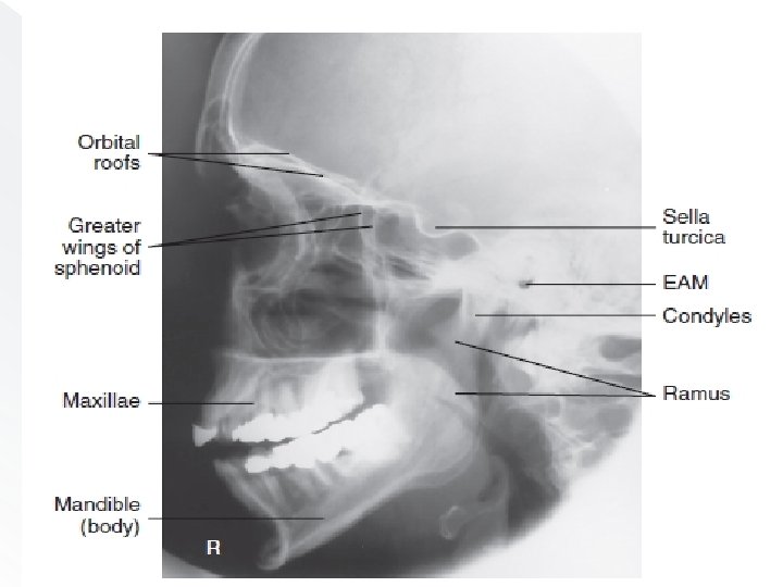
LATERAL POSITION—RIGHT OR LEFT LATERAL: � Clinical Indications Fractures and neoplastic or inflammatory processes of the facial bones, orbits, and mandible

� Patient Position Remove all metallic or plastic objects from head and neck. Patient position is erect or recumbent semi prone. Right lateral— recumbent. Right lateral—erect. RT lateral—recumbent.

Part Position • Rest lateral aspect of head against table or upright imaging device surface, with side of interest closest to IR. • Adjust head into a true lateral position and oblique body as needed for patient’s comfort. Place support sponge under chin if needed. • Align MS P parallel to IR. • Align IPL perpendicular to IR. • Adjust chin to bring IOML perpendicular to front edge of IR.
, midway between outer canthus and")
CR • Center CR to zygoma (prominence of thecheek), midway between outer canthus and EAM.

Lateral facial bones.

Evaluation Criteria Anatomy Demonstrated: • Superimposed facial bones, greater wings of the sphenoid, orbital roofs, sella turcica, zygoma, and mandible are demonstrated.

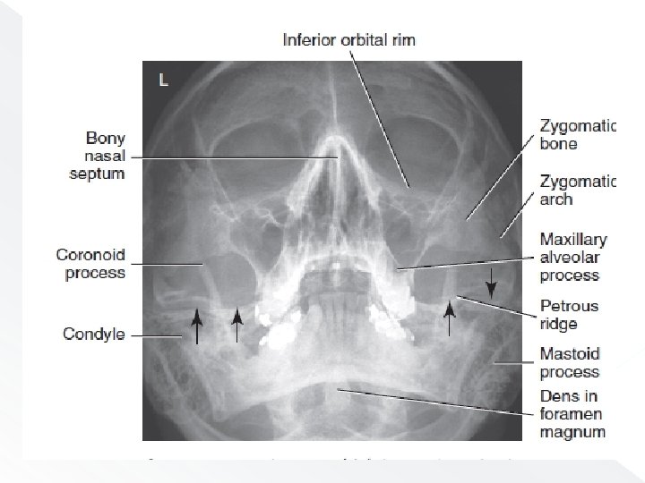
WATERS METHOD Parietoacanthial projection � Clinical Indications • Fractures and neoplastic or inflammatory processes • Foreign bodies in the eye

� Patient Position Remove all metallic or plastic objects from head and neck. Patient position is erect or prone (erect is preferred if patient’s condition allows).
—MML perpendicular (OML 37°).")
Parietoacanthial (Waters)—MML perpendicular (OML 37°).

� CR • Align CR perpendicular to IR, to exit at acanthion. • Center IR to CR.
— MML perpendicular (OML 37°)")
Parietoacanthial (Waters)— MML perpendicular (OML 37°)

Evaluation Criteria � Anatomy Demonstrated: • IOMs, maxillae, nasal septum, zygomatic bones, zygomatic arches, and anterior nasal spine

CALDWELL METHOD PA AXIAL PROJECTION � Clinical Indications • Fractures and neoplastic or inflammatory processes of the facial bones

Patient Position � Remove all metallic or plastic objects from head and neck. Patient position is erect or prone (erect is preferred if patient’s condition allows).

Fig PA axial Caldwell—OML perpendicular, CR 15° caudad.

Part Position • Rest patient’s nose and forehead against tabletop. • Tuck chin, bringing OML perpendicular to IR. • Align MS P perpendicular to midline of grid or table/imaging device surface. � Ensure no rotation or tilt of head.

�CR • Angle CR 15° caudad, to exit at nasion • Center CR to IR.

� NOTE: � If area of interest is the orbital floors, use a 30° caudad angle to project the petrous ridges below the IOM.

PA axial Caldwell—CR 15°.

Evaluation Criteria � Anatomy Demonstrated: • Orbital rim, maxillae, nasal septum, zygomatic bones, and anterior nasal spine
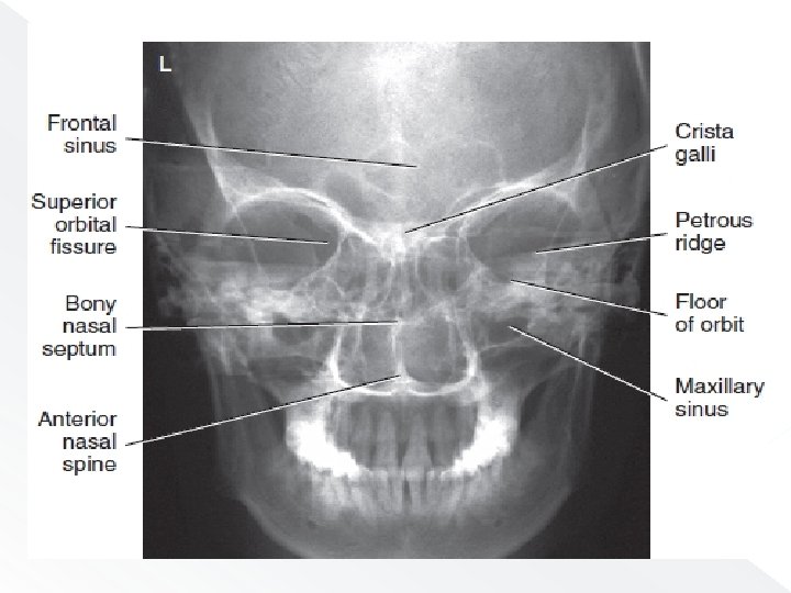

Position: � Correct patient position/CR angulation is indicated by petrous ridges projected into the lower one-third of orbits with 15° caudad CR. � No rotation of cranium is indicated by equal distance from midlateral orbital margin to the lateral cortex of the cranium; superior orbital fissures are symmetric

NASAL BONES
![Nasal Bones � ROUTINE lateral 2. Parietoacanthial [Waters method] 1.](http://slidetodoc.com/presentation_image_h2/e791c0a3caa65000acb5752a7cb6fb20/image-27.jpg "Nasal Bones � ROUTINE lateral 2. Parietoacanthial [Waters method] 1.")
Nasal Bones � ROUTINE lateral 2. Parietoacanthial [Waters method] 1.

LATERAL POSITION NASAL BONES Clinical Indications • Nasal bone fractures Both sides should be examined for comparison, with side closest to IR best demonstrated.
 • IR size— 18 ×")
Technical Factors • Minimum SID— 40 inches (102 cm) • IR size— 18 × 24 cm (8 × 10 inches), crosswise • Non grid

Patient Position Left lateral—prone or erect.
.")
Lateral (L and R).
 inferior to")
CR • Align CR perpendicular to IR. • Center (1. 25 cm) inferior to nasion. � Recommended Collimation Collimate on all sides to within 2 inches (5 cm) of nasal bone.

Evaluation Criteria Anatomy Demonstrated: • Nasal bones with soft tissue nasal structures, the frontonasal suture, and the anterior nasal spine are demonstrated. Position: • Nasal bones are demonstrated without rotation. • Collimation to area of interest. Exposure: • Contrast and density (brightness) are sufficient to visualize nasal bone and soft tissue structures. • Sharp bony structures indicate no motion
 projection special Clinical Indications • Fractures of the nasal bones (mediallateral")
Superoinferior tangential (axial) projection special Clinical Indications • Fractures of the nasal bones (mediallateral displacement)

� Patient Position Patient is seated erect in a chair at end of table or in the prone position on table.

Part Position • Extend and rest chin on IR. � Place angled support under IR, as demonstrated, to place IR perpendicular to GAL. • Align MSP perpendicular to CR and to IR midline.

CR • Center CR to nasion and angle as needed to ensure that it is parallel to GAL. �

Superoinferior projection

Superoinferior projection.

ZYGOMATIC ARCHES

Zygomatic Arches � ROUTINE SM V 2. oblique tangential 3. A P axial (modified. Towne method 1.

Clinical Indications • Fractures of zygomatic arch • Neoplastic or inflammatory processes
 • IR size— 18")
� Technical Factors • Minimum SID— 40 inches (102 cm) • IR size— 18 × 24 cm (8 × 10 inches), crosswise • Grid

Patient Position SMV projection, supine or erect—IOML parallel to IR ; CR perpendicular to IOML.

CR • Center CR midway between zygomatic arches, at a level 1 ½ inches (4 cm) inferior to mandibular symphysis. • Center IR to CR, with plane of IR parallel to IOML.

SMV projection

Evaluation Criteria � Anatomy Demonstrated: • Zygomatic arches are demonstrated laterally from each mandibular ramus.

� Position: • Correct IOML/CR relationship, as indicated by superimposition of mandibular symphysis on frontal bone. • No patient rotation, as indicated by zygomatic arches visualized symmetrically. • Collimation to area of interest. Exposure: • Sufficient contrast and density (brightness) to visualize zygomatic arches. • Sharp bony margins indicate no motion.

THANK WE WILL CONT……. NEXT
- Slides: 49