
Fabricating Microgeometry for Custom Surface Reflectance SIGGRAPH 2009
Fabricating Microgeometry for Custom Surface Reflectance SIGGRAPH 2009 August 4, New Orleans Tim Weyrich 1 Pieter Peers 2 Wojciech Matusik 3 1 Szymon Rusinkiewicz 3, 4 University College London 2 University of Southern California, Institute for Creative Technologies 3 Adobe Systems, Inc. 4 Princeton University
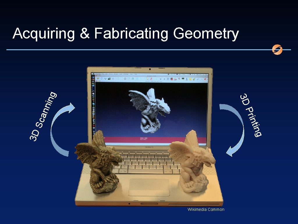
ing 3 D S can nin t Prin 3 D g Acquiring & Fabricating Geometry Wikimedia Common
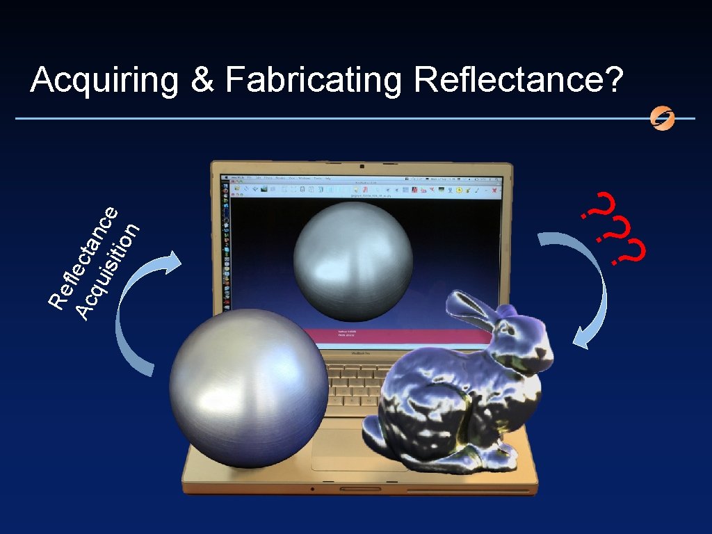
? ? ? Re fle Ac cta qu n isit ce ion Acquiring & Fabricating Reflectance?
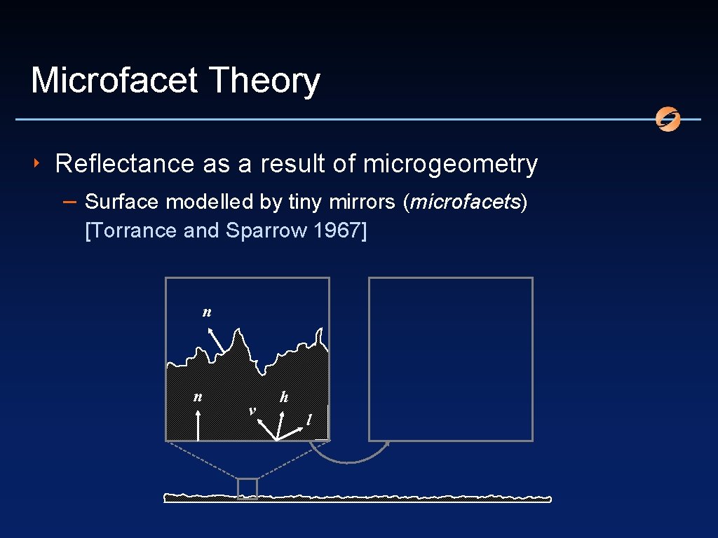
Microfacet Theory ‣ Reflectance as a result of microgeometry – Surface modelled by tiny mirrors (microfacets) [Torrance and Sparrow 1967] n n v h l
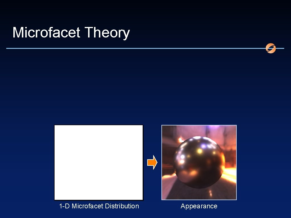
Microfacet Theory 1 -D Microfacet Distribution Appearance
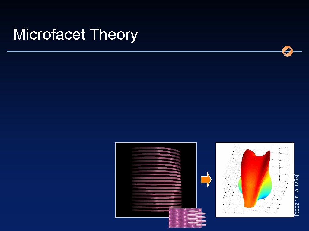
Microfacet Theory [Ngan et al. 2005]

Microfacet Theory
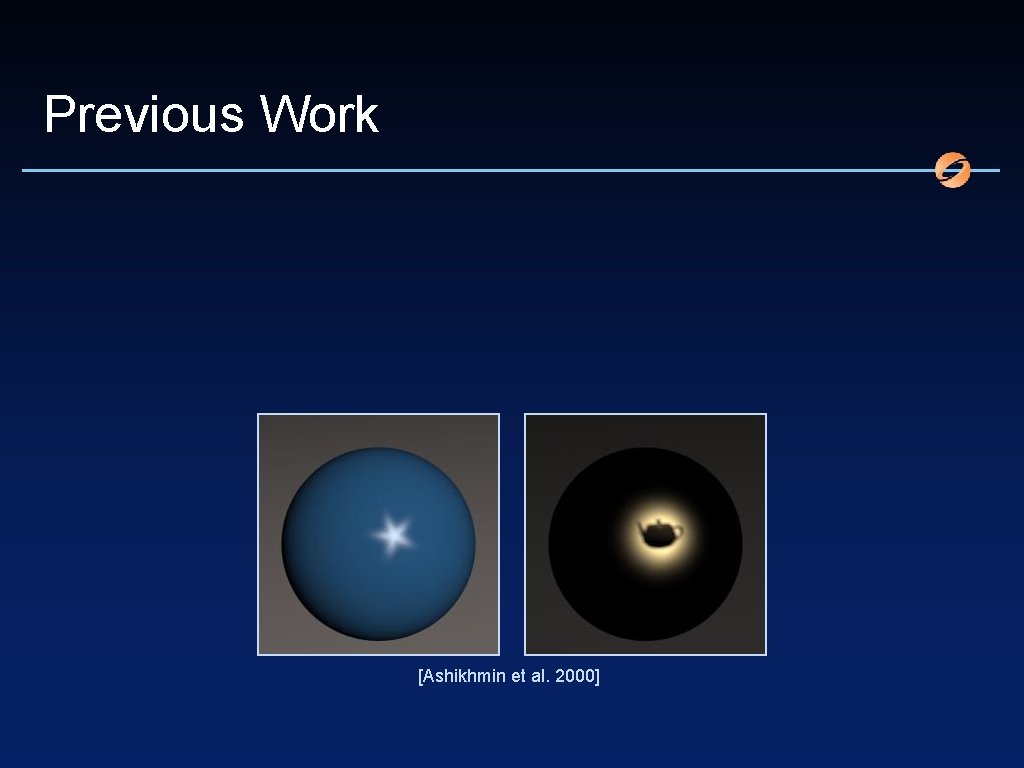
Previous Work [Ashikhmin et al. 2000]
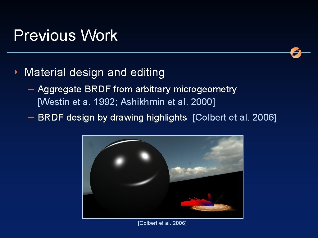
Previous Work ‣ Material design and editing – Aggregate BRDF from arbitrary microgeometry [Westin et a. 1992; Ashikhmin et al. 2000] – BRDF design by drawing highlights [Colbert et al. 2006]
Previous Work ‣ Material design and editing – Aggregate BRDF from arbitrary microgeometry [Westin et a. 1992; Ashikhmin et al. 2000] – BRDF design by drawing highlights [Colbert et al. 2006] – But no microgeometry from highlights
Previous Work ‣ Material design and editing – Aggregate BRDF from arbitrary microgeometry [Westin et a. 1992; Ashikhmin et al. 2000] – BRDF design by drawing highlights [Colbert et al. 2006] – But no microgeometry from highlights – Search for mirror geometry with target radiation [Patow and Pueyo 2005; Patow et al. 2007] – But fixed light source position and not planar [Patow and Pueyo. 2005] ‣ Reflector design
Previous Work ‣ Physical appearance output – 3 -D printing of artistic geometry [Séquin 2000] [Séquin 2005] – Bas-relief sculpture outputs – But no user-defined reflectance output [Weyrich et al. 2007] macroscopic appearance [Cignoni et al. 1997; Weyrich et al. 2007; Song et al. 2007; Kerber et al. 2007]
Problem Definition ‣ BRDF specification by microfacet distribution (MFD) ‣ Find microgeometry that – has normals that satisfy MFD – is a height field – is tileable (for efficiency) ‣ In a sense, MFD integration problem ‣ Related to Poisson problem – except that gradient locations not known
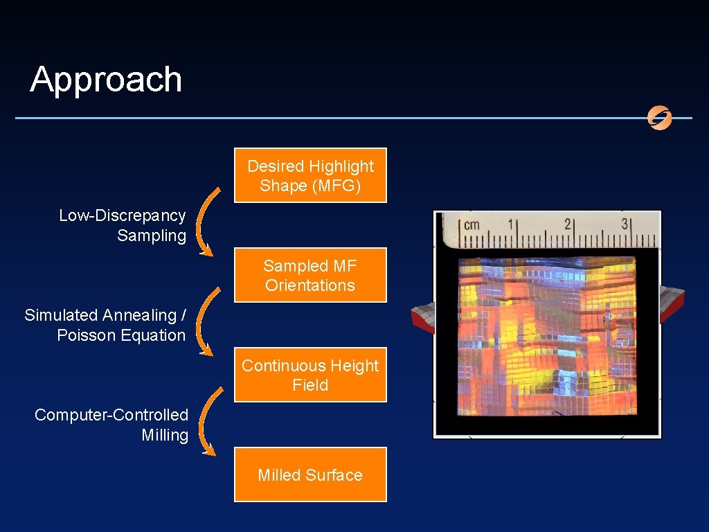
Approach Desired Highlight Shape (MFG) Low-Discrepancy Sampling Sampled MF Orientations Simulated Annealing / Poisson Equation Continuous Height Field Computer-Controlled Milling Milled Surface
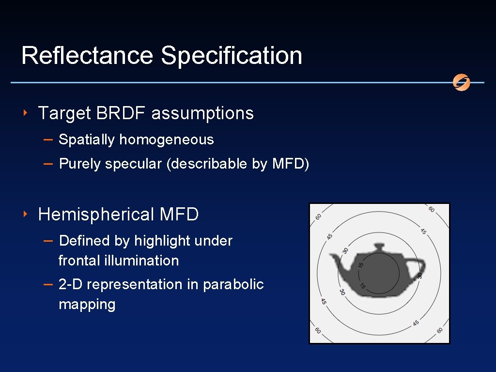
Reflectance Specification ‣ Target BRDF assumptions – Spatially homogeneous – Purely specular (describable by MFD) ‣ Hemispherical MFD – Defined by highlight under frontal illumination – 2 -D representation in parabolic mapping
Reflectance of Base Material ‣ Substrate exhibits own, base BRDF ‣ Altered reflectance by shaped microgeometry ‣ Net BRDF is convolution of MFD by base BRDF ‣ Goal: Shaping base material to exhibit aggregate target BRDF
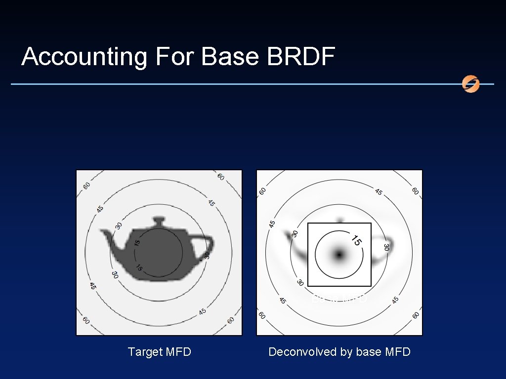
Accounting For Base BRDF Base MFD Target MFD Deconvolved by base MFD
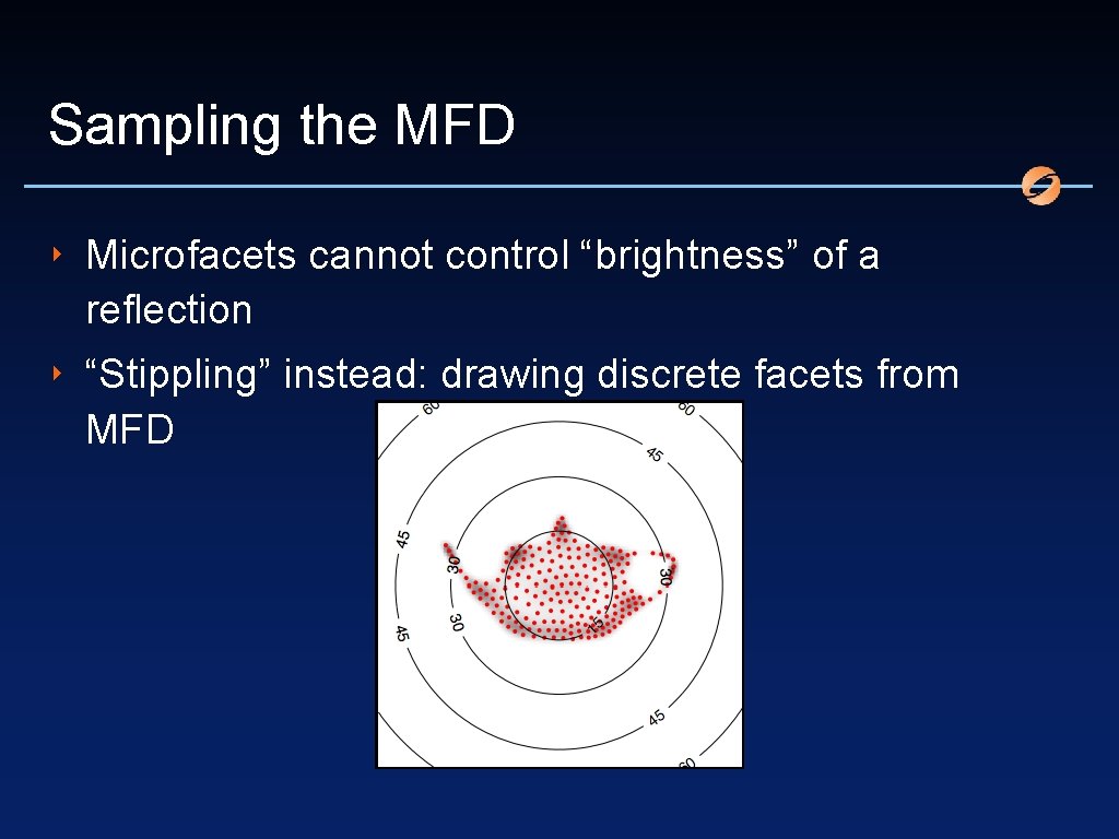
Sampling the MFD ‣ Microfacets cannot control “brightness” of a reflection ‣ “Stippling” instead: drawing discrete facets from MFD
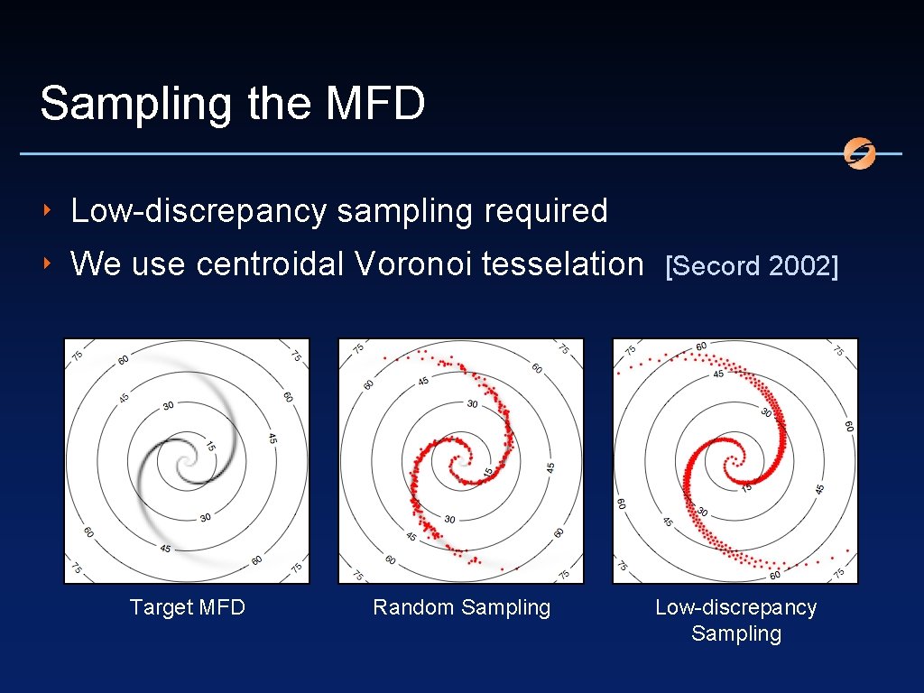
Sampling the MFD ‣ Low-discrepancy sampling required ‣ We use centroidal Voronoi tesselation [Secord 2002] Target MFD Random Sampling Low-discrepancy Sampling
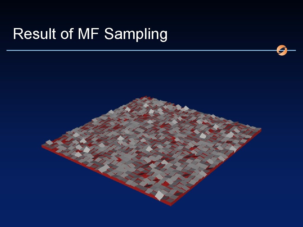
Result of MF Sampling
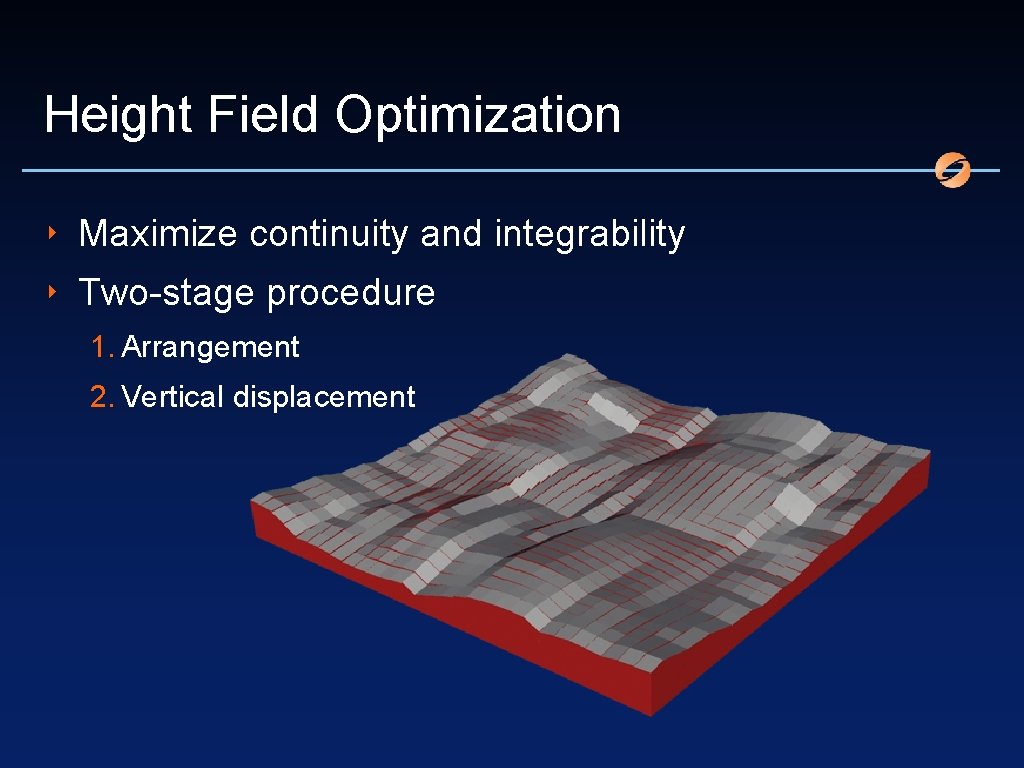
Height Field Optimization ‣ Maximize continuity and integrability ‣ Two-stage procedure 1. Arrangement 2. Vertical displacement
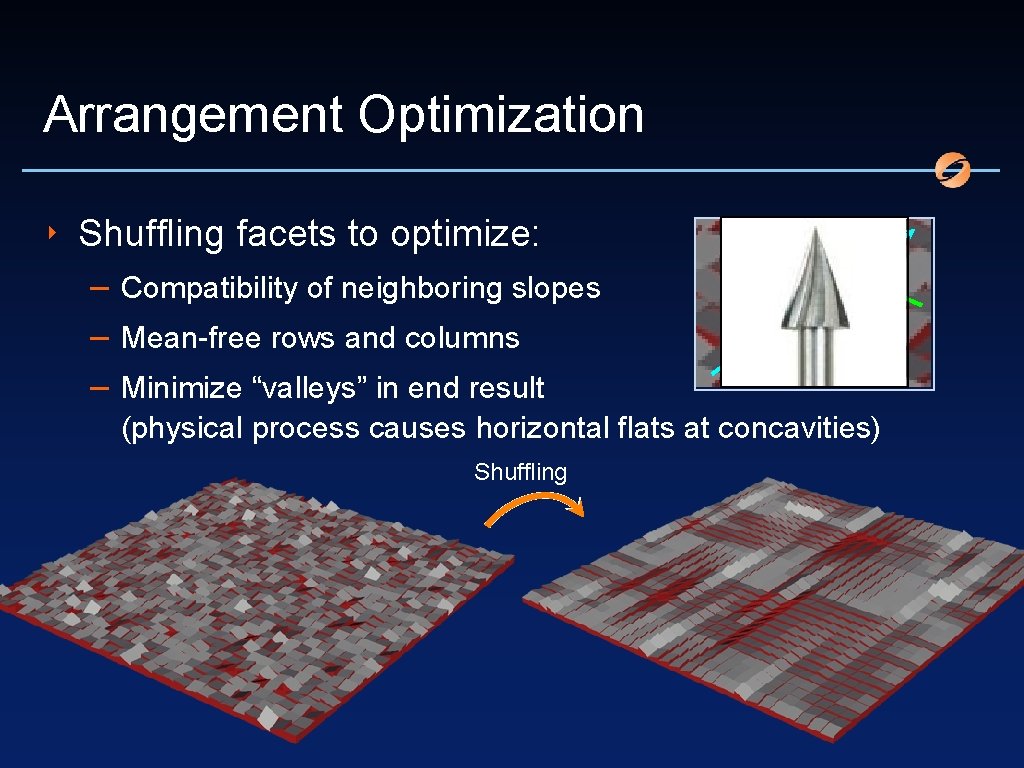
Arrangement Optimization ‣ Shuffling facets to optimize: – Compatibility of neighboring slopes – Mean-free rows and columns – Minimize “valleys” in end result (physical process causes horizontal flats at concavities) Shuffling
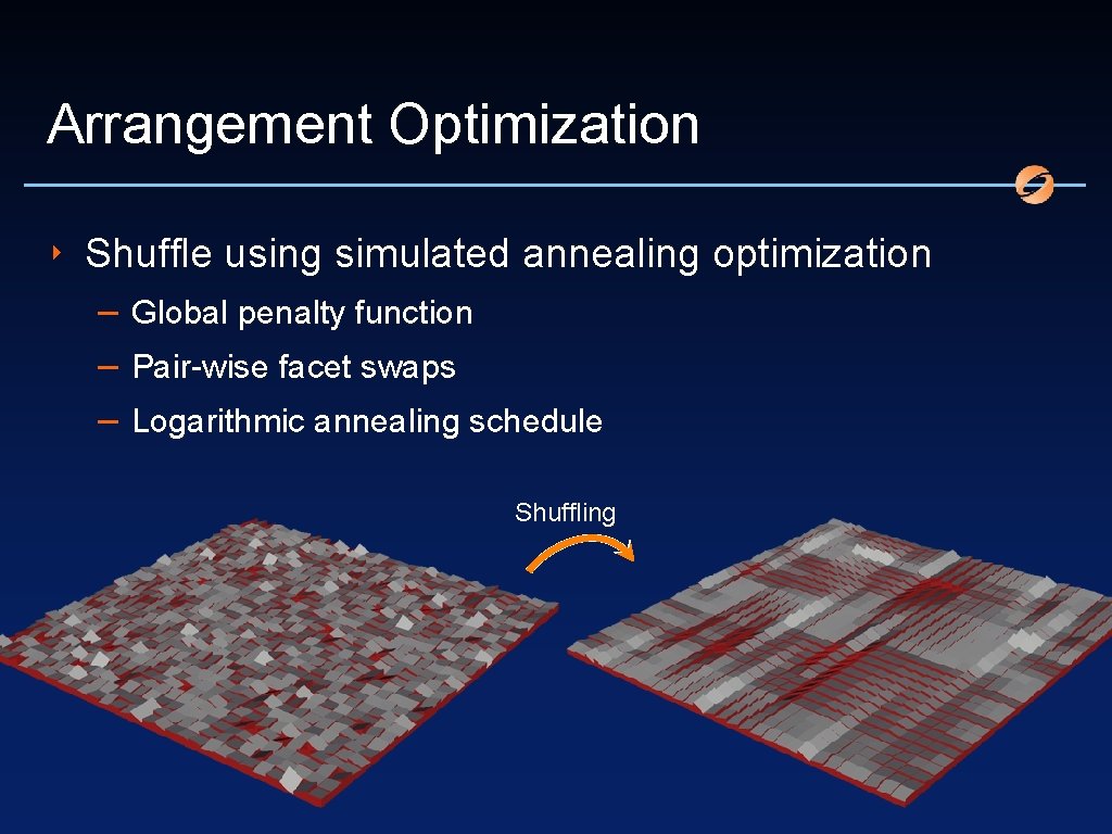
Arrangement Optimization ‣ Shuffle using simulated annealing optimization – Global penalty function – Pair-wise facet swaps – Logarithmic annealing schedule Shuffling
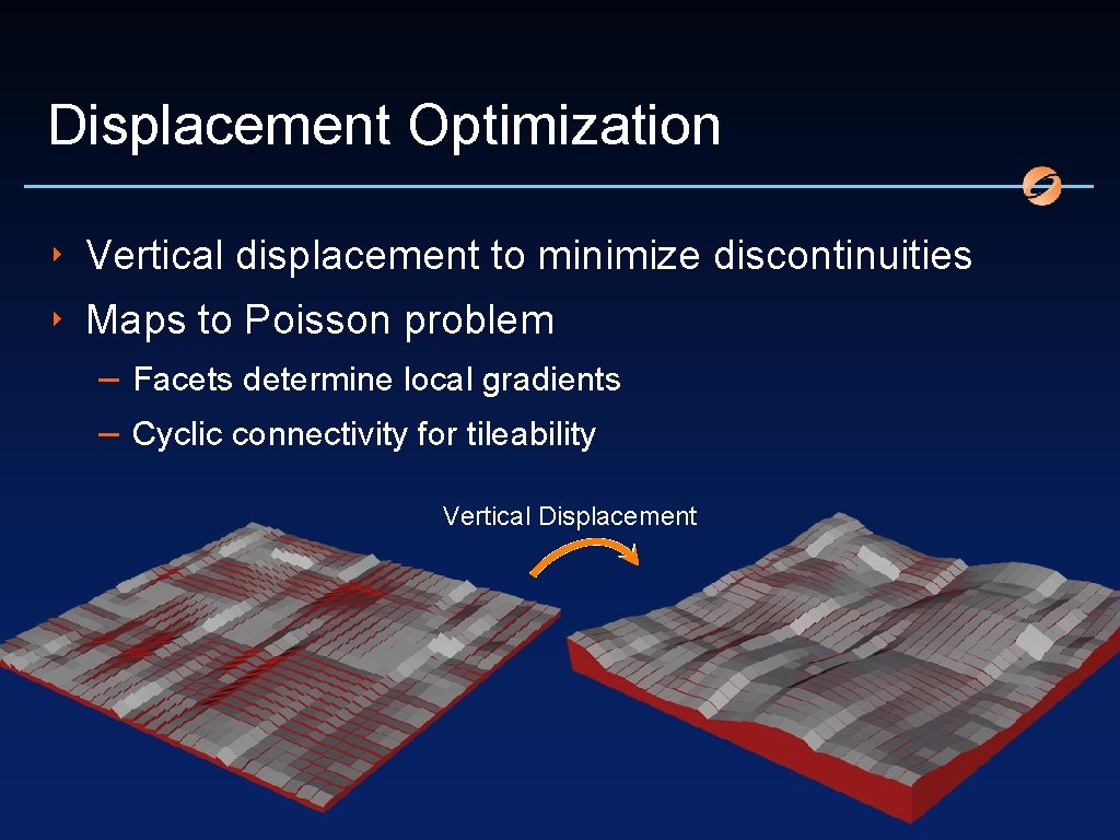
Displacement Optimization ‣ Vertical displacement to minimize discontinuities ‣ Maps to Poisson problem – Facets determine local gradients – Cyclic connectivity for tileability Vertical Displacement
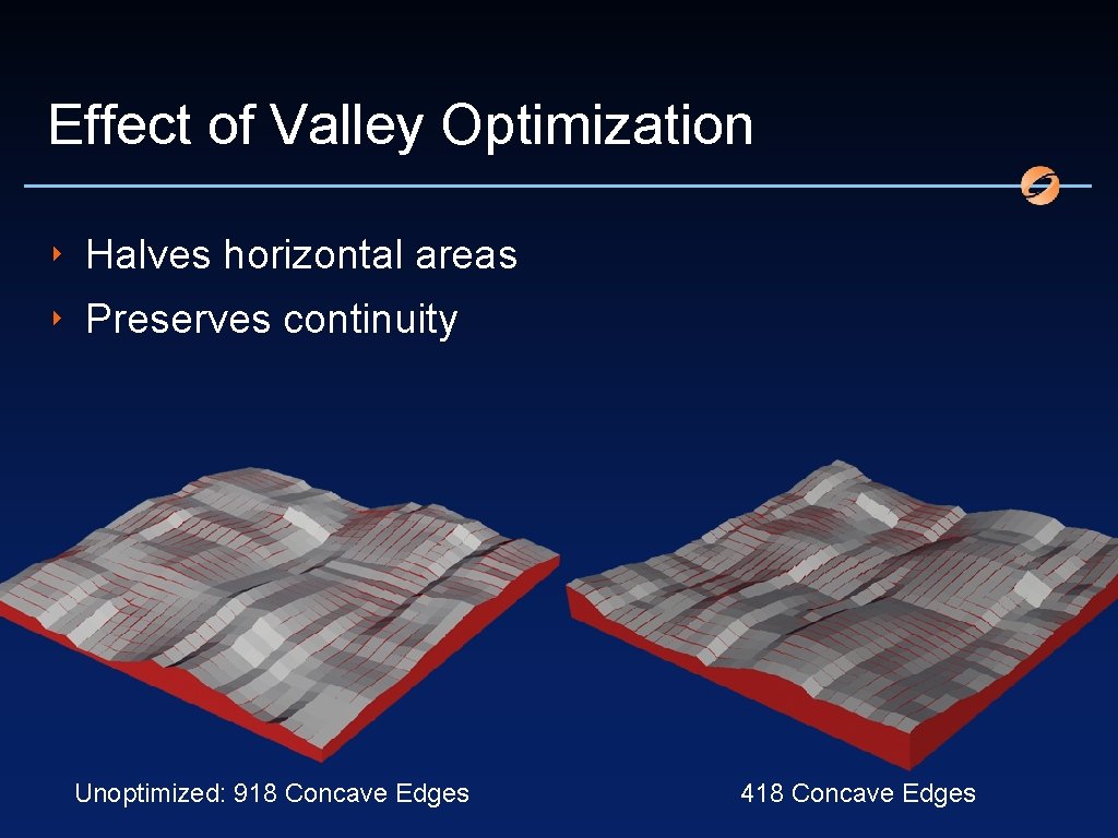
Effect of Valley Optimization ‣ Halves horizontal areas ‣ Preserves continuity Unoptimized: 918 Concave Edges 418 Concave Edges
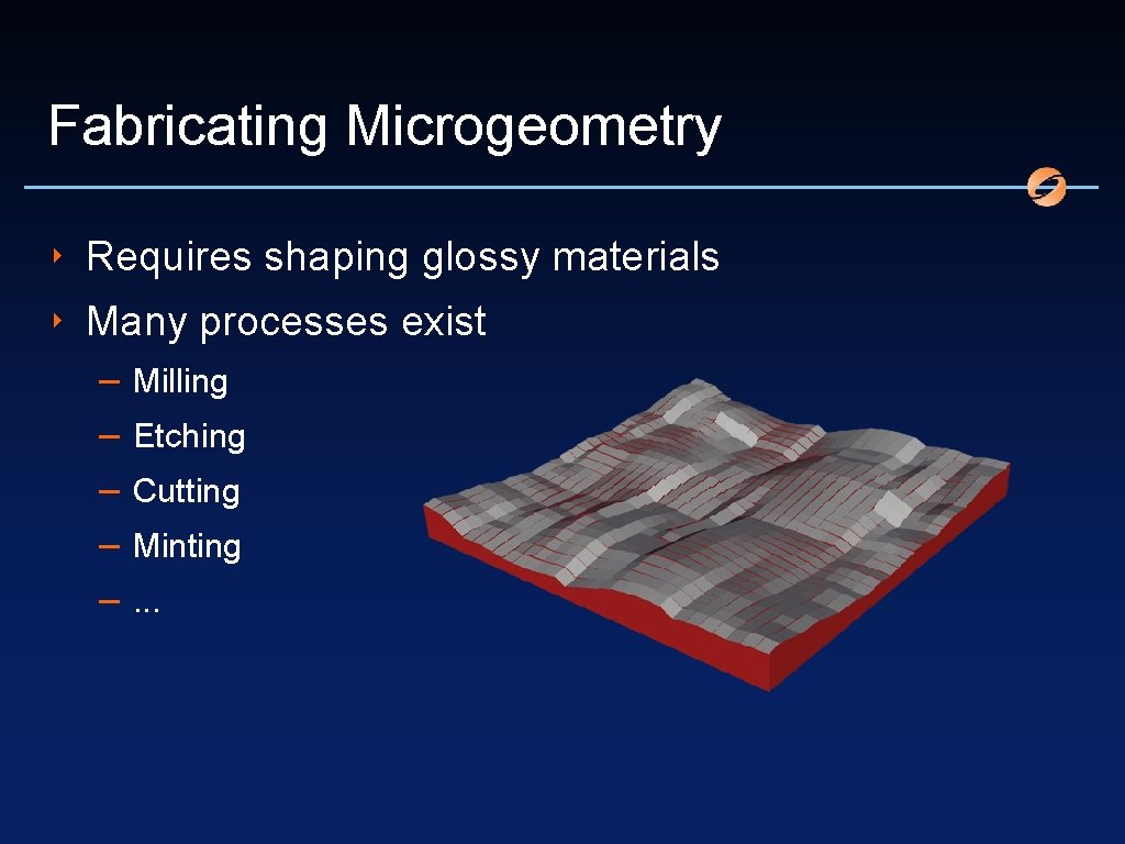
Fabricating Microgeometry ‣ Requires shaping glossy materials ‣ Many processes exist – – – Milling Etching Cutting Minting. . .
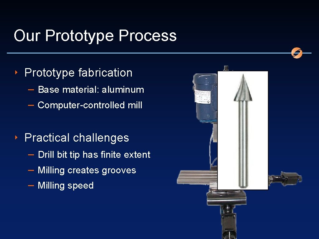
Our Prototype Process ‣ Prototype fabrication – Base material: aluminum – Computer-controlled mill ‣ Practical challenges – Drill bit tip has finite extent – Milling creates grooves – Milling speed
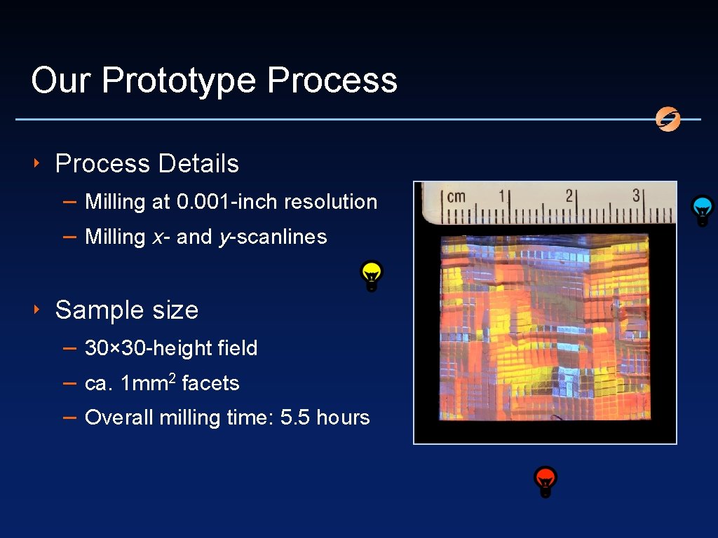
Our Prototype Process ‣ Process Details – Milling at 0. 001 -inch resolution – Milling x- and y-scanlines ‣ Sample size – 30× 30 -height field – ca. 1 mm 2 facets – Overall milling time: 5. 5 hours
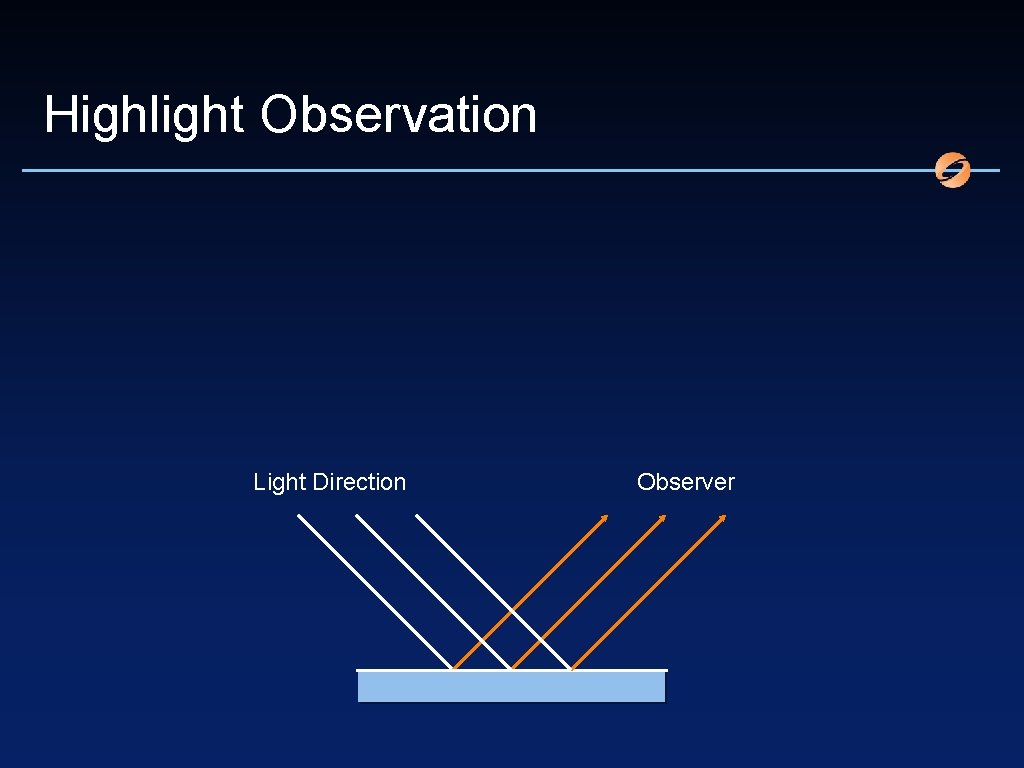
Highlight Observation Light Direction Observer
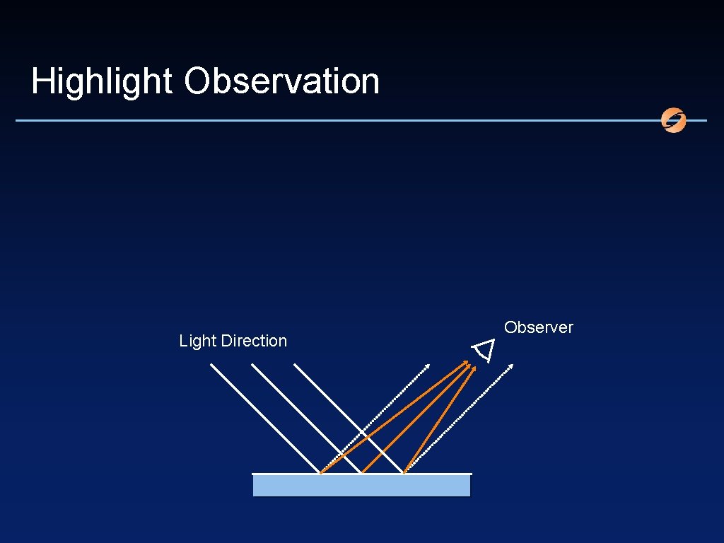
Highlight Observation Light Direction Observer
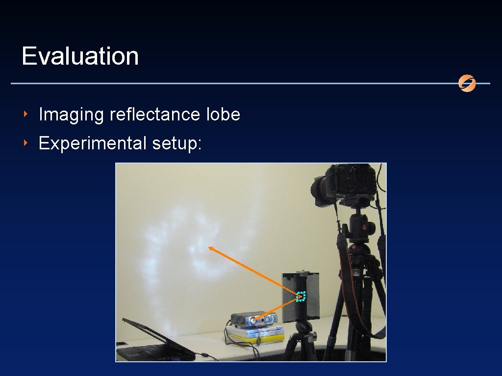
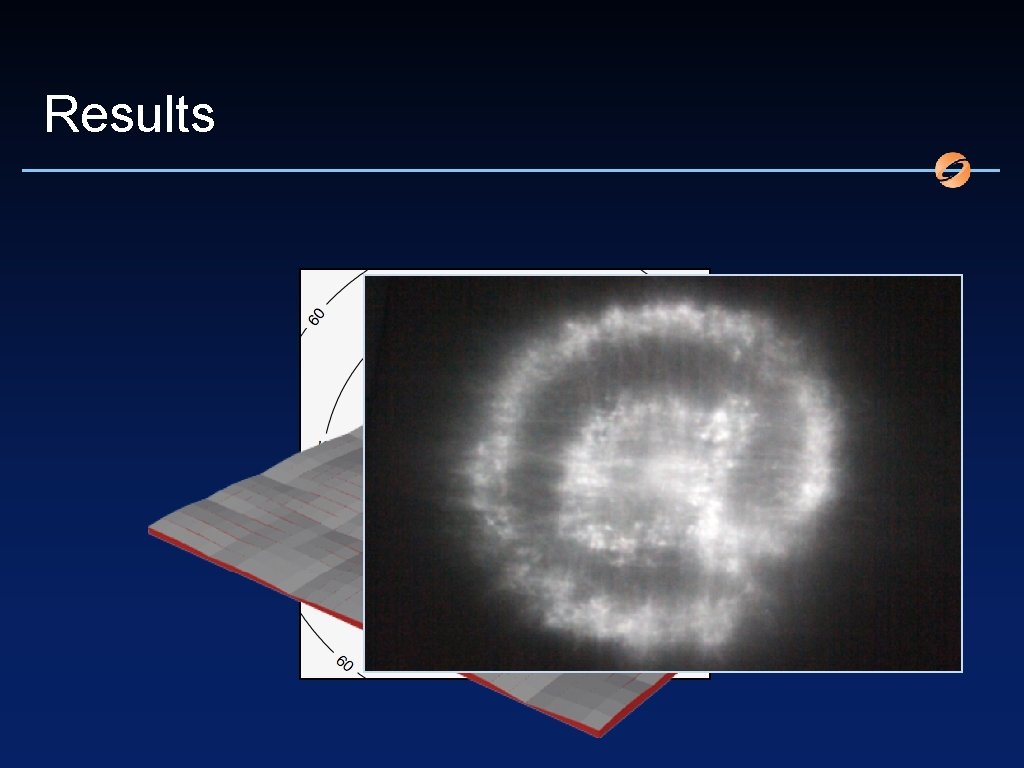
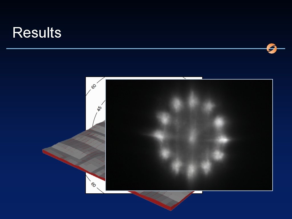
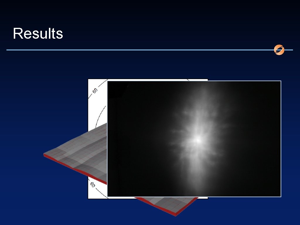
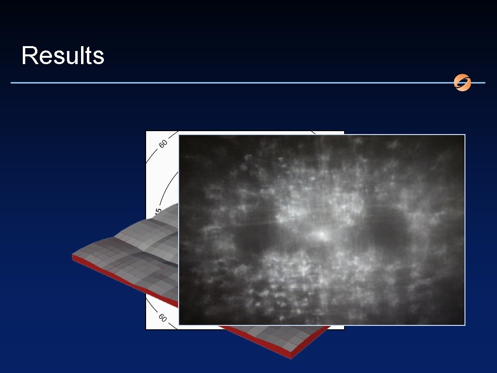
Evaluation ‣ Imaging reflectance lobe ‣ Experimental setup:
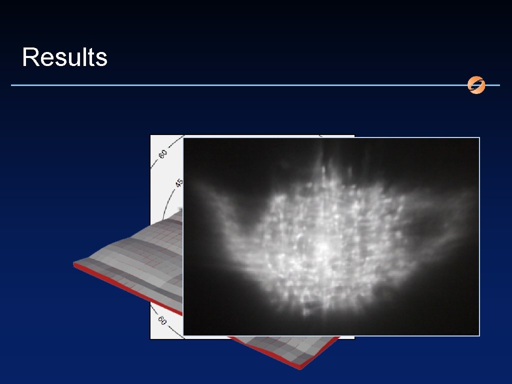
Results
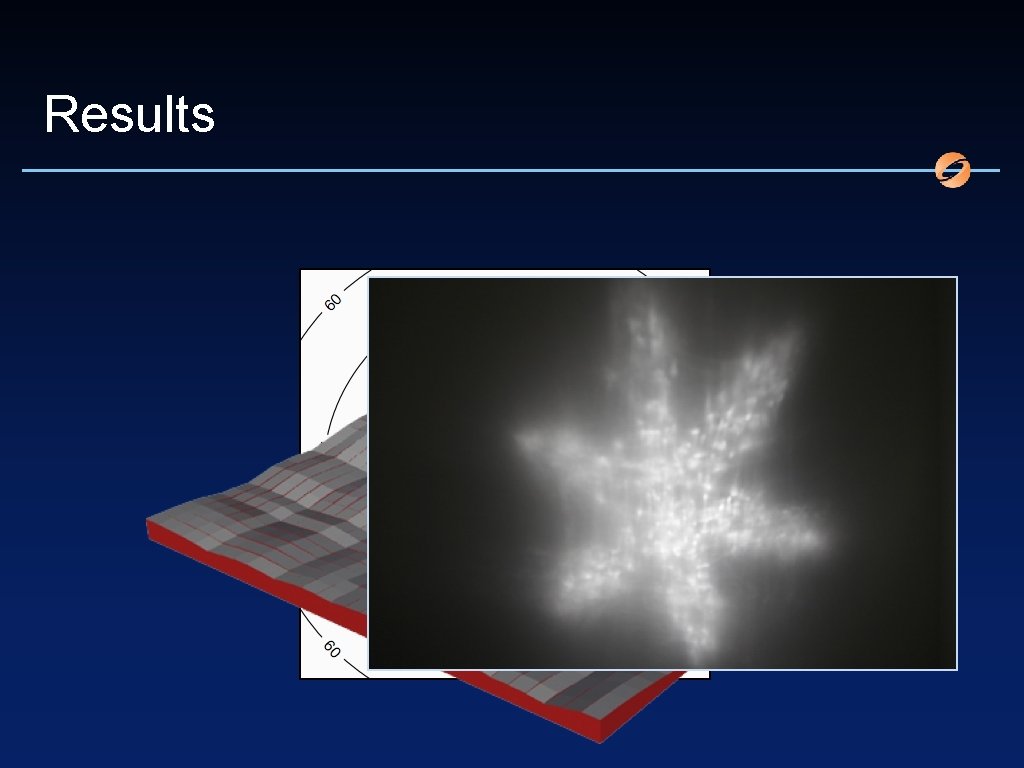
Results
Results
Results
Results
Results
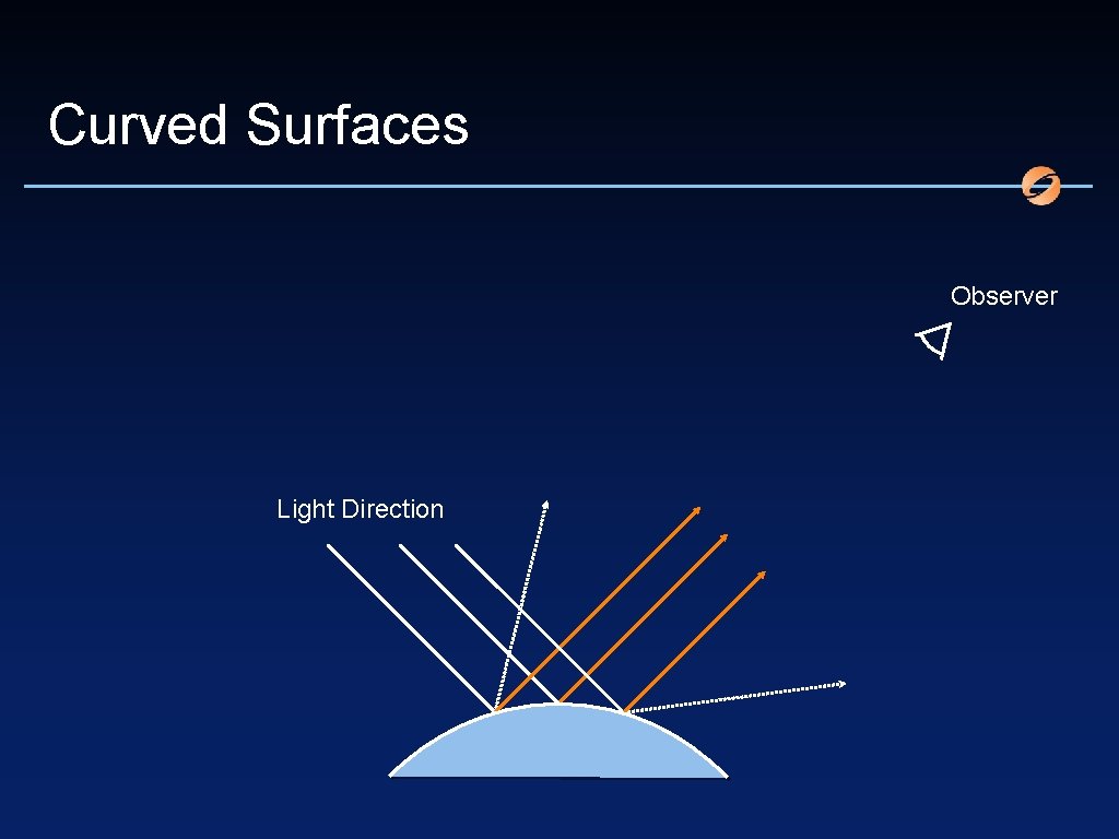
Curved Surfaces Observer Light Direction
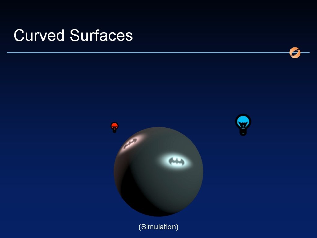
Curved Surfaces (Simulation)
Constraints ‣ Only integrable MFDs – Barycenter along surface normal – “What goes up has to go down” ‣ Purely specular reflectance ‣ Shadowing term implicit
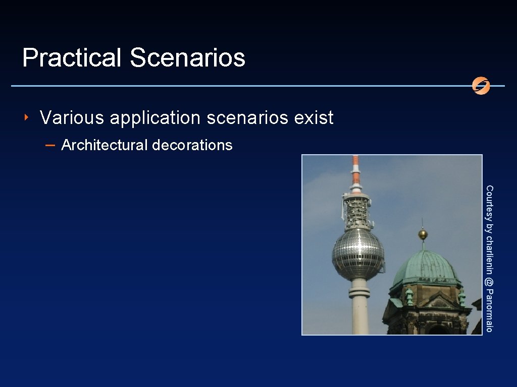
Practical Scenarios ‣ Various application scenarios exist – Architectural decorations Courtesy by charlienin @ Panormaio
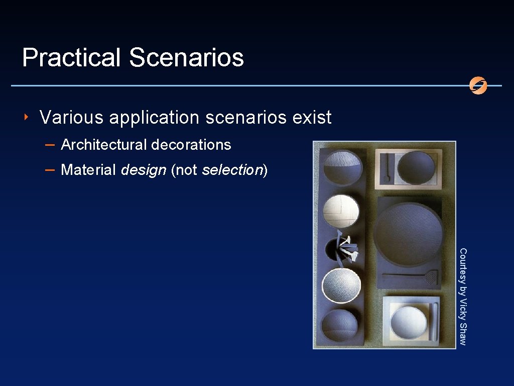
Practical Scenarios ‣ Various application scenarios exist – Architectural decorations – Material design (not selection) Courtesy by Vicky Shaw
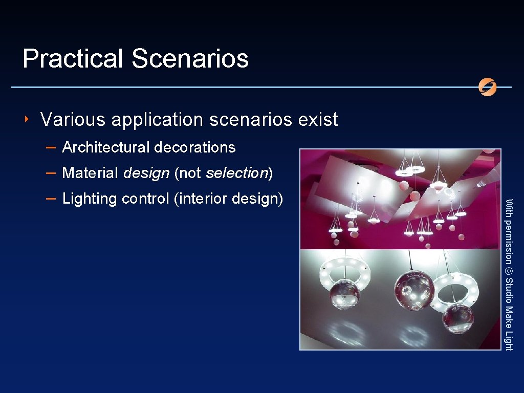
Practical Scenarios ‣ Various application scenarios exist With permission ⓒ Studio Make Light – Architectural decorations – Material design (not selection) – Lighting control (interior design)
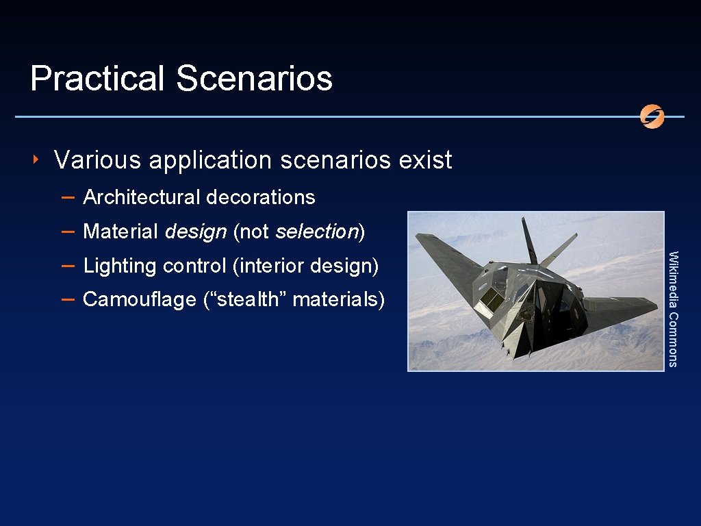
Practical Scenarios ‣ Various application scenarios exist Architectural decorations Material design (not selection) Lighting control (interior design) Camouflage (“stealth” materials) Wikimedia Commons – –
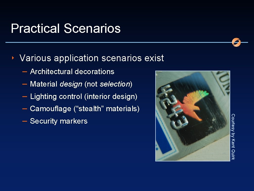
Practical Scenarios ‣ Various application scenarios exist Architectural decorations Material design (not selection) Lighting control (interior design) Camouflage (“stealth” materials) Security markers Courtesy by Kent Quirk – – –
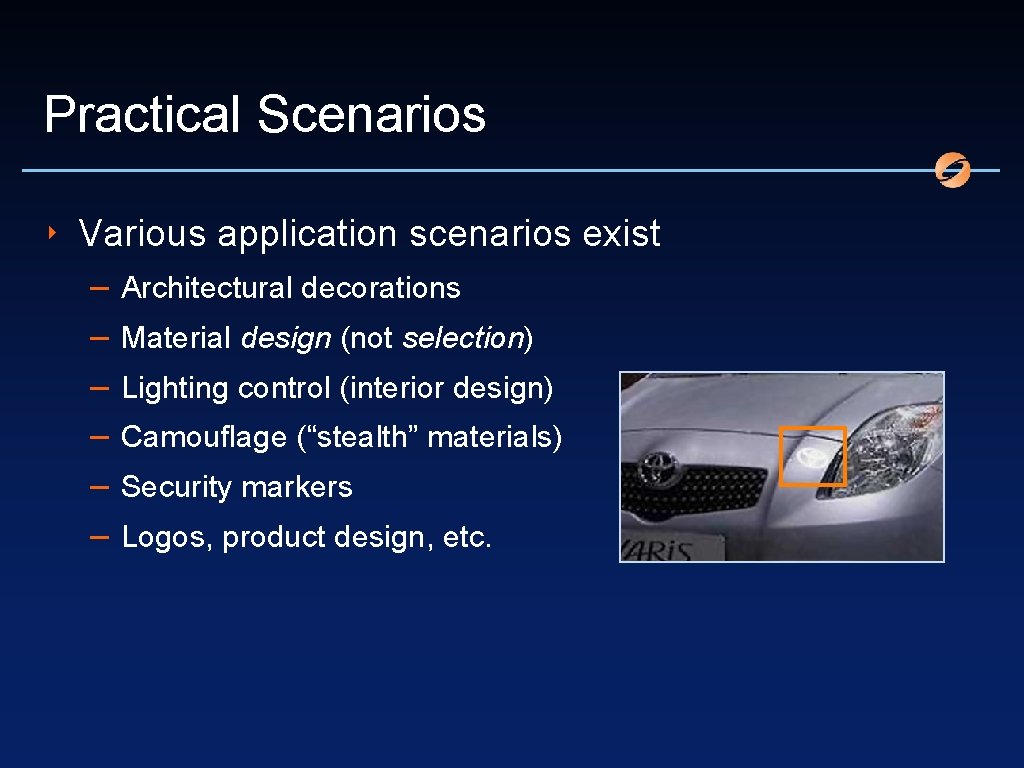
Practical Scenarios ‣ Various application scenarios exist – – – Architectural decorations Material design (not selection) Lighting control (interior design) Camouflage (“stealth” materials) Security markers Logos, product design, etc.
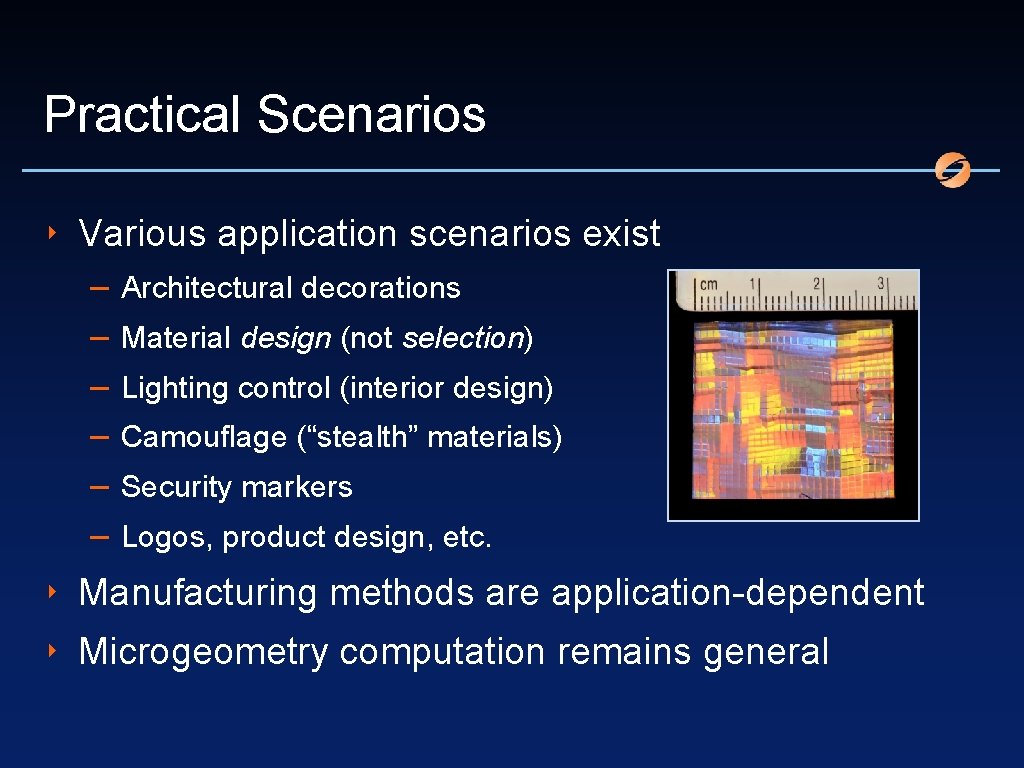
Practical Scenarios ‣ Various application scenarios exist – – – Architectural decorations Material design (not selection) Lighting control (interior design) Camouflage (“stealth” materials) Security markers Logos, product design, etc. ‣ Manufacturing methods are application-dependent ‣ Microgeometry computation remains general
Acknowledgments The content of the information does not necessarily reflect the position or the policy of the US Government, and no official endorsement should be inferred.
- Slides: 48