
EXTRAORAL RADIOGRAPH anatomic landmarks DEPARTMENT OF ORAL MEDICINE





- Slides: 84
EXTRA-ORAL RADIOGRAPH anatomic landmarks DEPARTMENT OF ORAL MEDICINE & RADIOLOGY Dentistry Explorer
Contents: • • • Introduction Indication Drawback Basic requirement Procedure Views for maxillofacial imaging Dentistry Explorer
Introduction • Both the X-ray source and the image receptor placed outside the mouth against the side of the face to be radiographed and the X-ray beam is directed towards it. • Radiographs can be taken with: – Conventional intraoral unit – Panoramic machine – Higher capacity medical X-ray unit Dentistry Explorer
Indications When not possible to place film intraorally To examine the extent of large lesions When jaws or other facial bones have to be examined for evidence of disease and pathological conditions To evaluate skeletal growth and development To evaluate the status of impacted teeth To evaluate trauma To evaluate the TMJ region Dentistry Explorer
Drawbacks • Magnification due to greater object to film distance • Details not well defined due to indirect exposure • Contrast reduced due to secondary radiation produced by soft tissue Dentistry Explorer
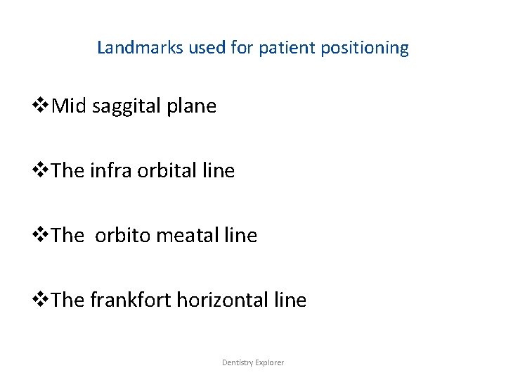
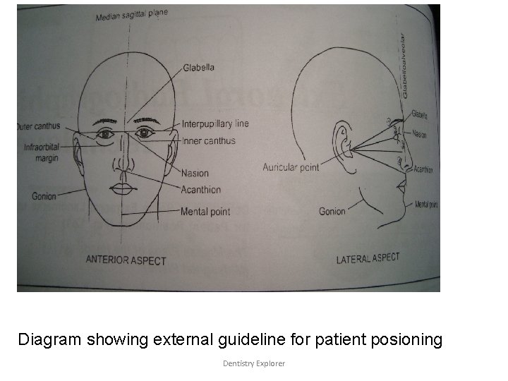
Landmarks used for patient positioning v. Mid saggital plane v. The infra orbital line v. The orbito meatal line v. The frankfort horizontal line Dentistry Explorer
Diagram showing external guideline for patient posioning Dentistry Explorer
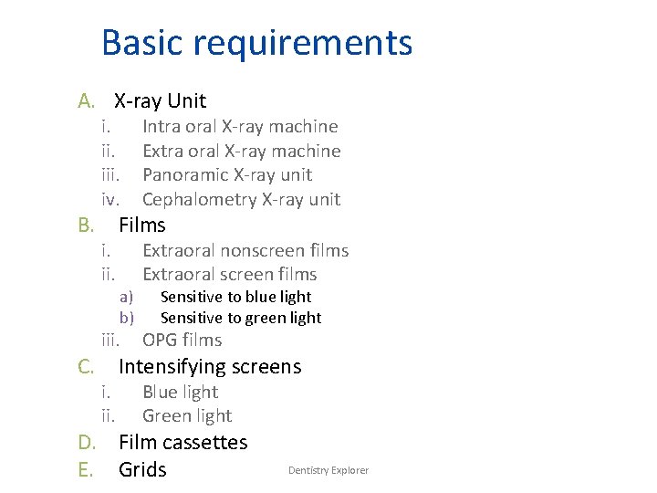
Basic requirements A. X-ray Unit i. iii. iv. Intra oral X-ray machine Extra oral X-ray machine Panoramic X-ray unit Cephalometry X-ray unit i. ii. Extraoral nonscreen films Extraoral screen films B. Films a) b) Sensitive to blue light Sensitive to green light iii. OPG films i. ii. Blue light Green light C. Intensifying screens D. Film cassettes E. Grids Dentistry Explorer
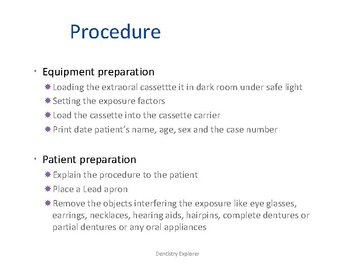
Procedure Equipment preparation Loading the extraoral cassettte it in dark room under safe light Setting the exposure factors Load the cassette into the cassette carrier Print date patient’s name, age, sex and the case number Patient preparation Explain the procedure to the patient Place a Lead apron Remove the objects interfering the exposure like eye glasses, earrings, necklaces, hearing aids, hairpins, complete dentures or partial dentures or any oral appliances Dentistry Explorer
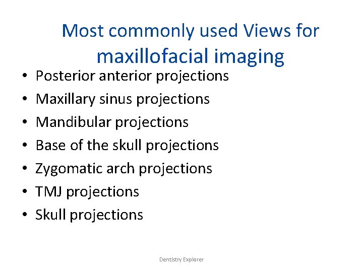
Most commonly used Views for • • maxillofacial imaging Posterior anterior projections Maxillary sinus projections Mandibular projections Base of the skull projections Zygomatic arch projections TMJ projections Skull projections Dentistry Explorer
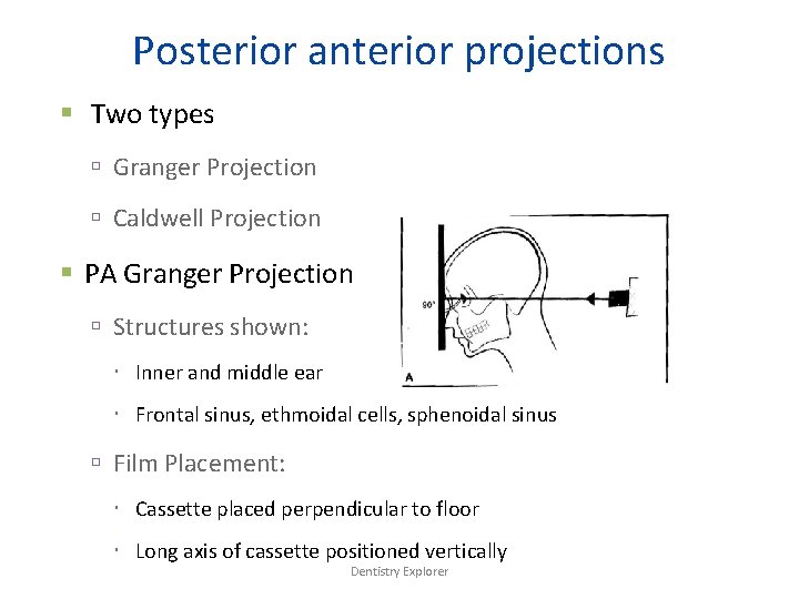
Posterior anterior projections Two types Granger Projection Caldwell Projection PA Granger Projection Structures shown: Inner and middle ear Frontal sinus, ethmoidal cells, sphenoidal sinus Film Placement: Cassette placed perpendicular to floor Long axis of cassette positioned vertically Dentistry Explorer
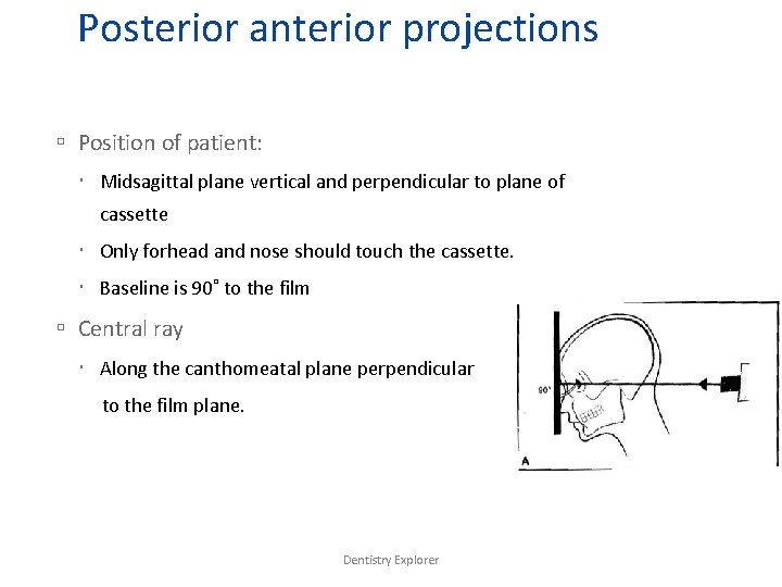
Posterior anterior projections Position of patient: Midsagittal plane vertical and perpendicular to plane of cassette Only forhead and nose should touch the cassette. Baseline is 90˚ to the film Central ray Along the canthomeatal plane perpendicular to the film plane. Dentistry Explorer
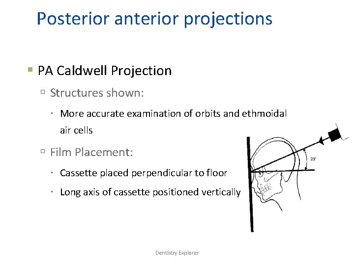
Posterior anterior projections PA Caldwell Projection Structures shown: More accurate examination of orbits and ethmoidal air cells Film Placement: Cassette placed perpendicular to floor Long axis of cassette positioned vertically Dentistry Explorer
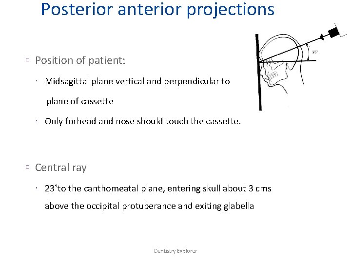
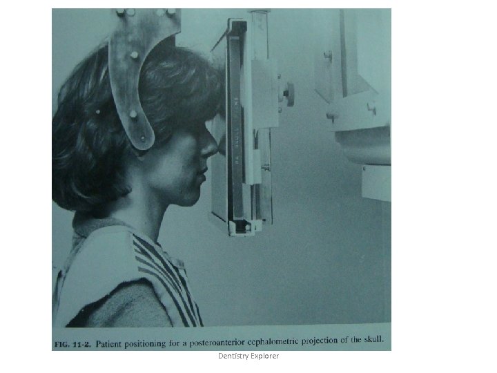
Posterior anterior projections Position of patient: Midsagittal plane vertical and perpendicular to plane of cassette Only forhead and nose should touch the cassette. Central ray 23˚to the canthomeatal plane, entering skull about 3 cms above the occipital protuberance and exiting glabella Dentistry Explorer
Dentistry Explorer
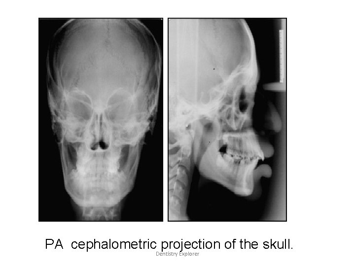
PA cephalometric projection of the skull. Dentistry Explorer
Maxillary sinus projections Four types Standard Occipitomental Projection 0˚ OM Modified Occipitomental Projection 30 ˚ OM Bregma Menton Projection PA Water’s Projection Dentistry Explorer
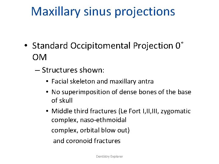
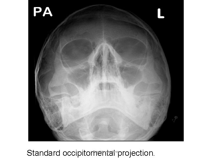
Maxillary sinus projections • Standard Occipitomental Projection 0˚ OM – Structures shown: • Facial skeleton and maxillary antra • No superimposition of dense bones of the base of skull • Middle third fractures (Le Fort I, III, zygomatic complex, naso-ethmoidal complex, orbital blow out) and coronoid fractures Dentistry Explorer
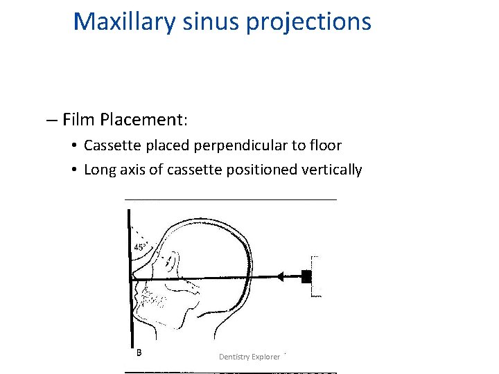
Maxillary sinus projections – Film Placement: • Cassette placed perpendicular to floor • Long axis of cassette positioned vertically Dentistry Explorer
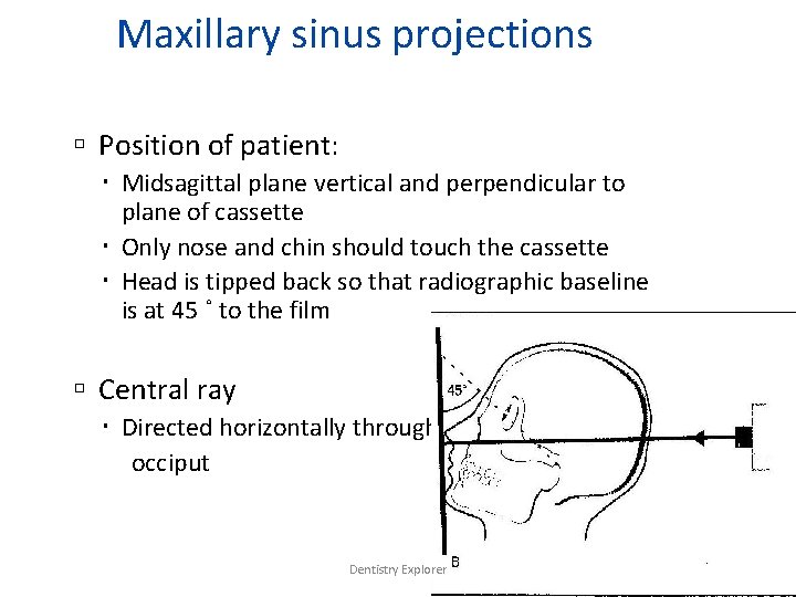
Maxillary sinus projections Position of patient: Midsagittal plane vertical and perpendicular to plane of cassette Only nose and chin should touch the cassette Head is tipped back so that radiographic baseline is at 45 ˚ to the film Central ray Directed horizontally through occiput Dentistry Explorer
Dentistry Explorer Standard occipitomental projection.
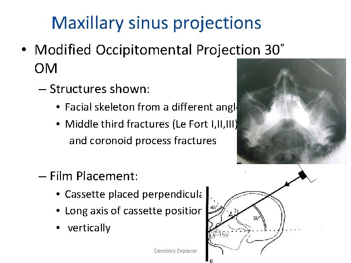
Maxillary sinus projections • Modified Occipitomental Projection 30˚ OM – Structures shown: • Facial skeleton from a different angle • Middle third fractures (Le Fort I, III) and coronoid process fractures – Film Placement: • Cassette placed perpendicular to floor • Long axis of cassette positioned • vertically Dentistry Explorer
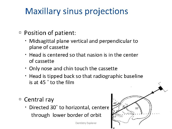
Maxillary sinus projections Position of patient: Midsagittal plane vertical and perpendicular to plane of cassette Head is centered so that nasion is in the center of cassette Only nose and chin touch the cassette Head is tipped back so that radiographic baseline is at 45 ˚ to the film Central ray Directed 30˚ to horizontal, centered through lower border of orbit Dentistry Explorer
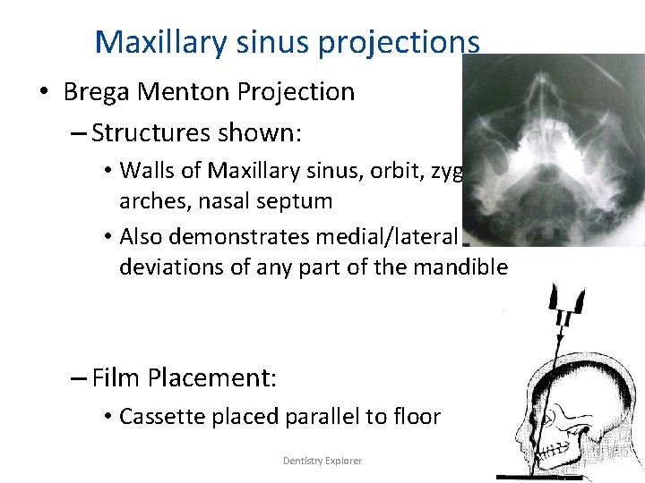
Maxillary sinus projections • Brega Menton Projection – Structures shown: • Walls of Maxillary sinus, orbit, zygomatic arches, nasal septum • Also demonstrates medial/lateral deviations of any part of the mandible – Film Placement: • Cassette placed parallel to floor Dentistry Explorer
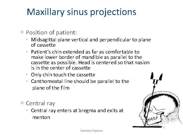
Maxillary sinus projections Position of patient: Midsagittal plane vertical and perpendicular to plane of cassette Patient’s chin extended as far as comfortable to make lower border of mandible as parallel to the cassette as possible. Head is centered so that nasion is in the center of cassette Only chin touch the cassette Canthomeatal line should be parallel to the plane of the film Central ray enters at bregma and exits at menton Dentistry Explorer
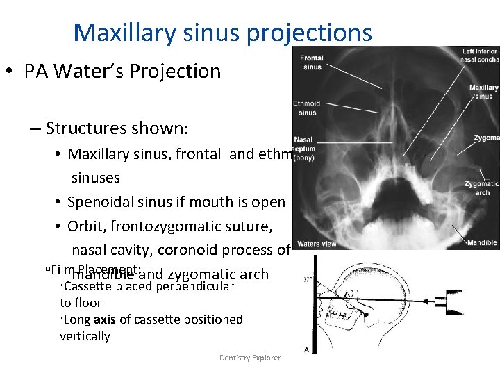
Maxillary sinus projections • PA Water’s Projection – Structures shown: • Maxillary sinus, frontal and ethmoidal sinuses • Spenoidal sinus if mouth is open • Orbit, frontozygomatic suture, nasal cavity, coronoid process of Filmmandible Placement: and zygomatic arch Cassette placed perpendicular to floor Long axis of cassette positioned vertically Dentistry Explorer
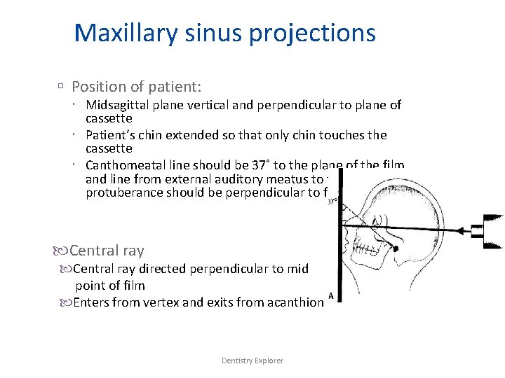
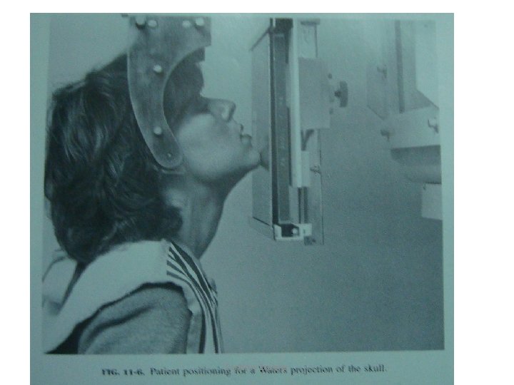
Maxillary sinus projections Position of patient: Midsagittal plane vertical and perpendicular to plane of cassette Patient’s chin extended so that only chin touches the cassette Canthomeatal line should be 37˚ to the plane of the film and line from external auditory meatus to the mental protuberance should be perpendicular to film Central ray directed perpendicular to mid point of film Enters from vertex and exits from acanthion Dentistry Explorer
Dentistry Explorer
Mandibular projections • Three types – PA Mandible – Rotated PA Mandible – Lateral Oblique • Anterior Body • Posterior Body • Ramus Dentistry Explorer
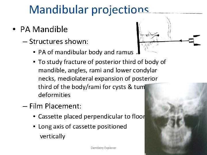
Mandibular projections • PA Mandible – Structures shown: • PA of mandibular body and ramus • To study fracture of posterior third of body of mandible, angles, rami and lower condylar necks, mediolateral expansion of posterior third of the body/rami for cysts & tumours, deformities – Film Placement: • Cassette placed perpendicular to floor • Long axis of cassette positioned vertically Dentistry Explorer
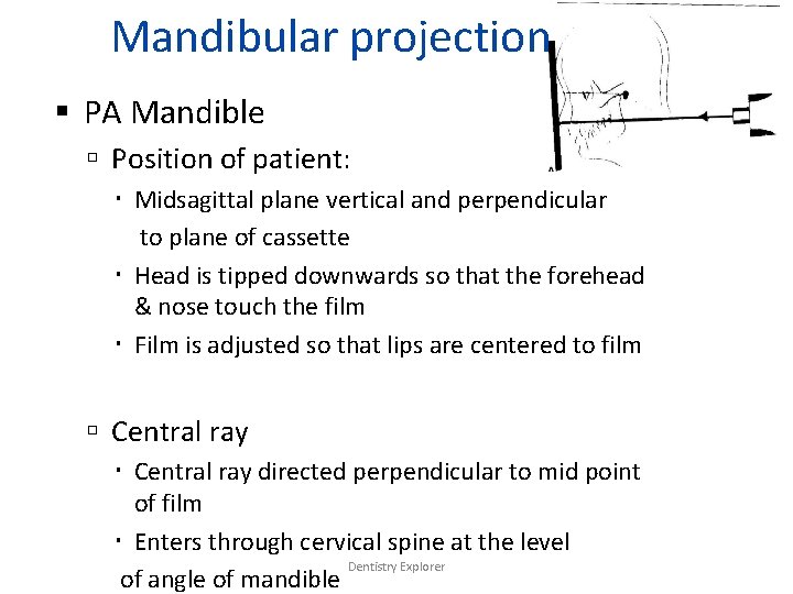
Mandibular projections PA Mandible Position of patient: Midsagittal plane vertical and perpendicular to plane of cassette Head is tipped downwards so that the forehead & nose touch the film Film is adjusted so that lips are centered to film Central ray directed perpendicular to mid point of film Enters through cervical spine at the level Dentistry Explorer of angle of mandible
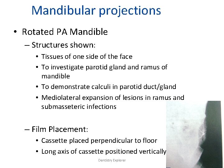
Mandibular projections • Rotated PA Mandible – Structures shown: • Tissues of one side of the face • To investigate parotid gland ramus of mandible • To demonstrate calculi in parotid duct/gland • Mediolateral expansion of lesions in ramus and submasseteric infections – Film Placement: • Cassette placed perpendicular to floor • Long axis of cassette positioned vertically Dentistry Explorer
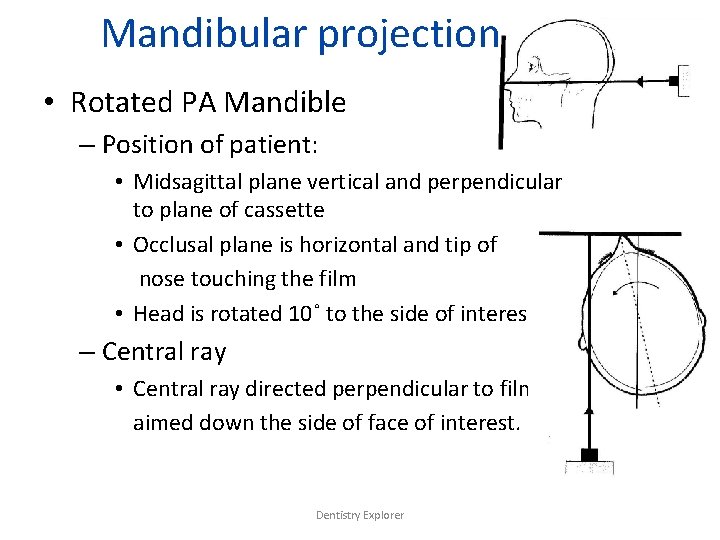
Mandibular projections • Rotated PA Mandible – Position of patient: • Midsagittal plane vertical and perpendicular to plane of cassette • Occlusal plane is horizontal and tip of nose touching the film • Head is rotated 10˚ to the side of interest. – Central ray • Central ray directed perpendicular to film aimed down the side of face of interest. Dentistry Explorer
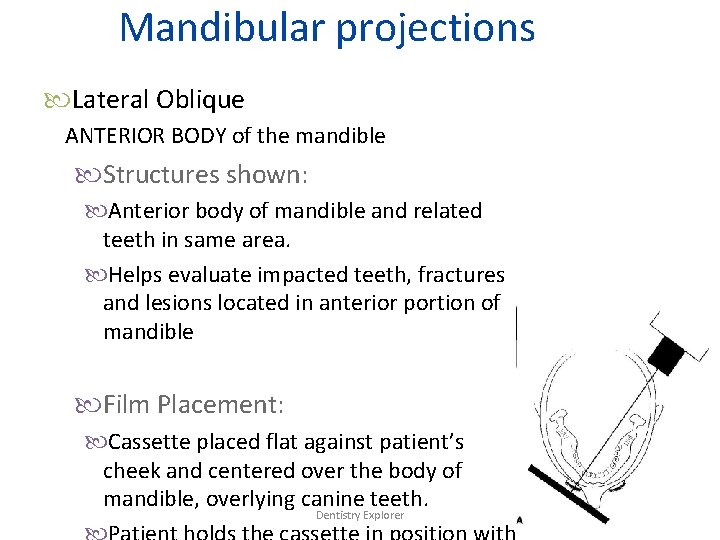
Mandibular projections Lateral Oblique ANTERIOR BODY of the mandible Structures shown: Anterior body of mandible and related teeth in same area. Helps evaluate impacted teeth, fractures and lesions located in anterior portion of mandible Film Placement: Cassette placed flat against patient’s cheek and centered over the body of mandible, overlying canine teeth. Dentistry Explorer
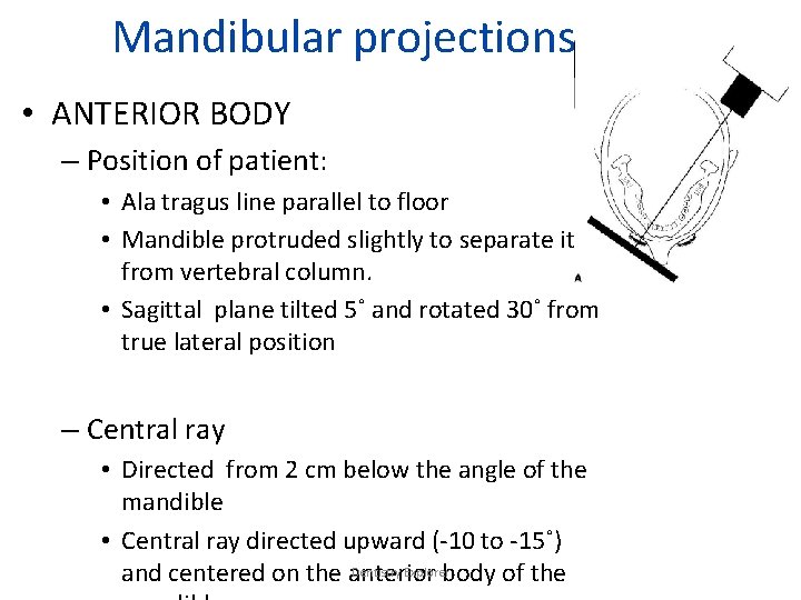
Mandibular projections • ANTERIOR BODY – Position of patient: • Ala tragus line parallel to floor • Mandible protruded slightly to separate it from vertebral column. • Sagittal plane tilted 5˚ and rotated 30˚ from true lateral position – Central ray • Directed from 2 cm below the angle of the mandible • Central ray directed upward (-10 to -15˚) Dentistry Explorer and centered on the anterior body of the
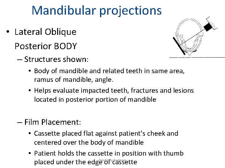
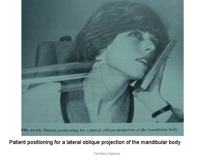
Mandibular projections • Lateral Oblique Posterior BODY – Structures shown: • Body of mandible and related teeth in same area, ramus of mandible, angle. • Helps evaluate impacted teeth, fractures and lesions located in posterior portion of mandible – Film Placement: • Cassette placed flat against patient’s cheek and centered over the body of mandible • Patient holds the cassette in position with thumb Dentistry Explorer placed under the edge of cassette
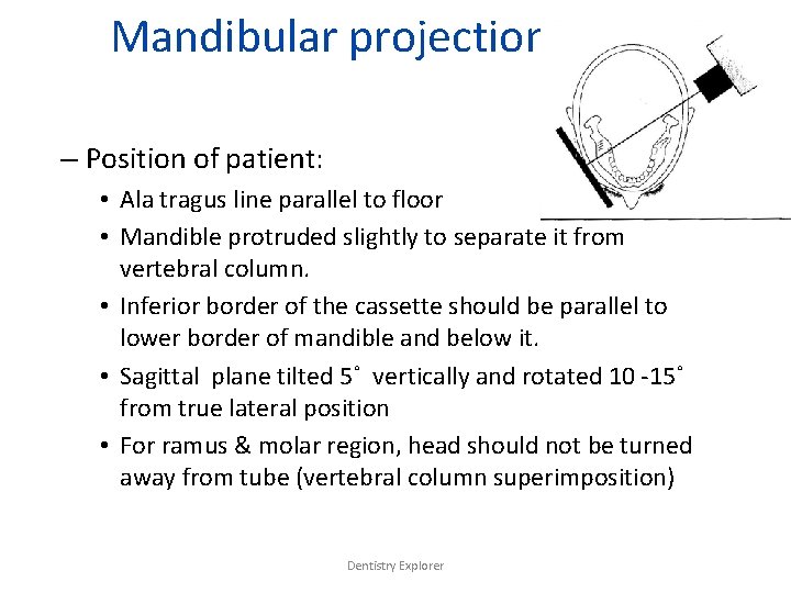
Mandibular projections – Position of patient: • Ala tragus line parallel to floor • Mandible protruded slightly to separate it from vertebral column. • Inferior border of the cassette should be parallel to lower border of mandible and below it. • Sagittal plane tilted 5˚ vertically and rotated 10 -15˚ from true lateral position • For ramus & molar region, head should not be turned away from tube (vertebral column superimposition) Dentistry Explorer
Mandibular projections – Central ray • Directed from 2 cm below the angle of the mandible • Central ray directed upward (-10 to -15˚) and centered on the body of the mandible • Beam perpendicular to horizontal plane of film Dentistry Explorer
Patient positioning for a lateral oblique projection of the mandibular body Dentistry Explorer
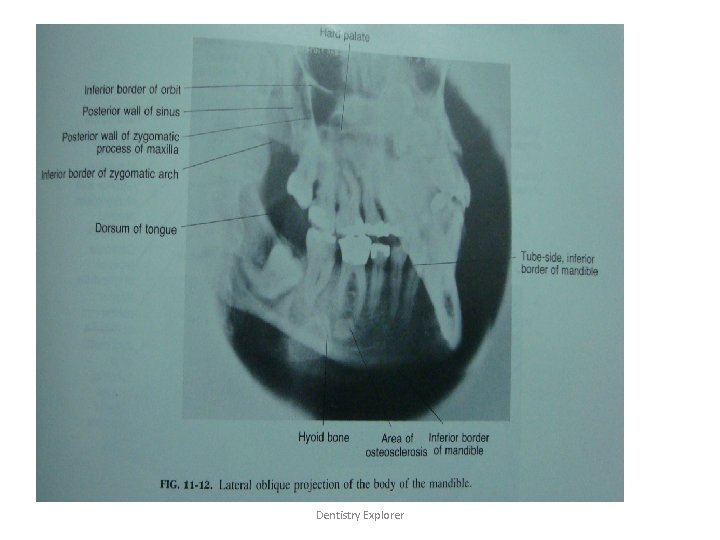
Lateral oblique projection of the body of mandible Dentistry Explorer
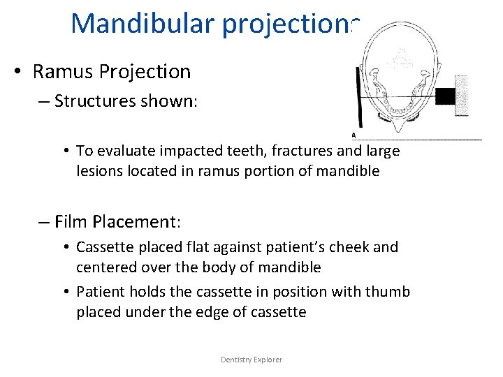
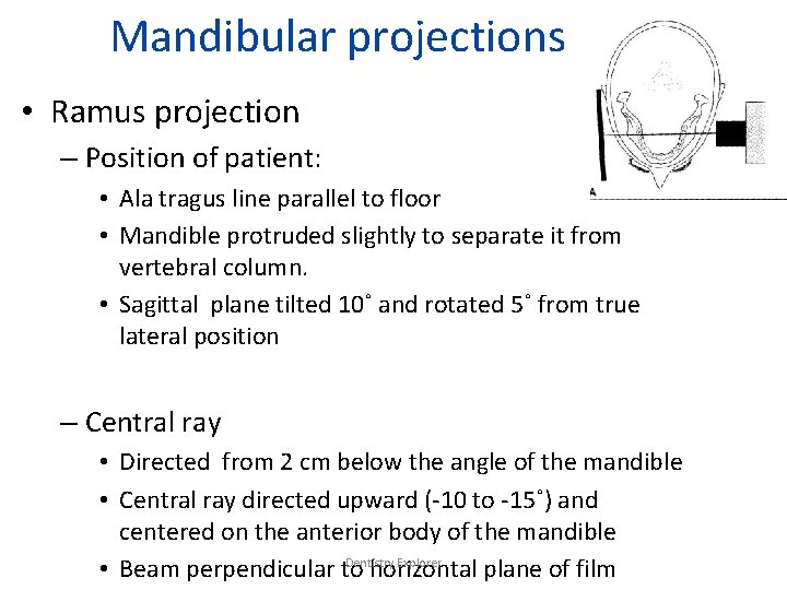
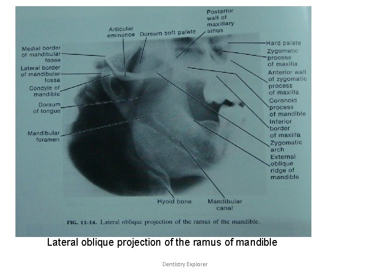
Mandibular projections • Ramus Projection – Structures shown: • To evaluate impacted teeth, fractures and large lesions located in ramus portion of mandible – Film Placement: • Cassette placed flat against patient’s cheek and centered over the body of mandible • Patient holds the cassette in position with thumb placed under the edge of cassette Dentistry Explorer
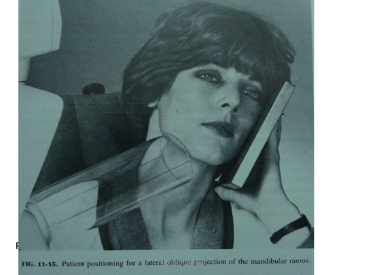
Mandibular projections • Ramus projection – Position of patient: • Ala tragus line parallel to floor • Mandible protruded slightly to separate it from vertebral column. • Sagittal plane tilted 10˚ and rotated 5˚ from true lateral position – Central ray • Directed from 2 cm below the angle of the mandible • Central ray directed upward (-10 to -15˚) and centered on the anterior body of the mandible Dentistry Explorer • Beam perpendicular to horizontal plane of film
Patient positioning for a lateral oblique projection of the mandibular ramus Dentistry Explorer
Lateral oblique projection of the ramus of mandible Dentistry Explorer
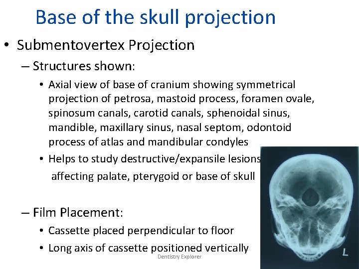
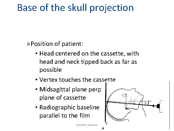
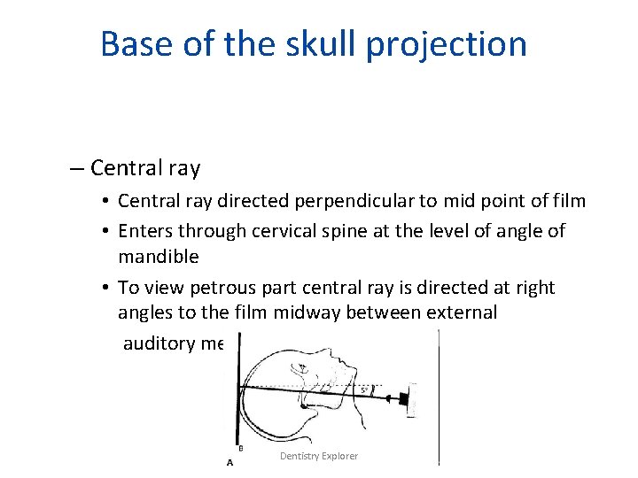
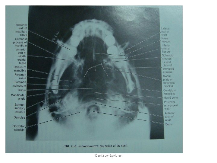
Base of the skull projection • Submentovertex Projection – Structures shown: • Axial view of base of cranium showing symmetrical projection of petrosa, mastoid process, foramen ovale, spinosum canals, carotid canals, sphenoidal sinus, mandible, maxillary sinus, nasal septom, odontoid process of atlas and mandibular condyles • Helps to study destructive/expansile lesions affecting palate, pterygoid or base of skull – Film Placement: • Cassette placed perpendicular to floor • Long axis of cassette positioned vertically Dentistry Explorer
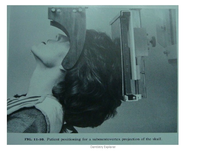
Base of the skull projection » Position of patient: • Head centered on the cassette, with head and neck tipped back as far as possible • Vertex touches the cassette • Midsagittal plane perpendicular to plane of cassette • Radiographic baseline should be parallel to the film Dentistry Explorer
Base of the skull projection – Central ray • Central ray directed perpendicular to mid point of film • Enters through cervical spine at the level of angle of mandible • To view petrous part central ray is directed at right angles to the film midway between external auditory meatus Dentistry Explorer
Patient positioning for a submento vertex projection of the skull Dentistry Explorer
Dentistry Explorer
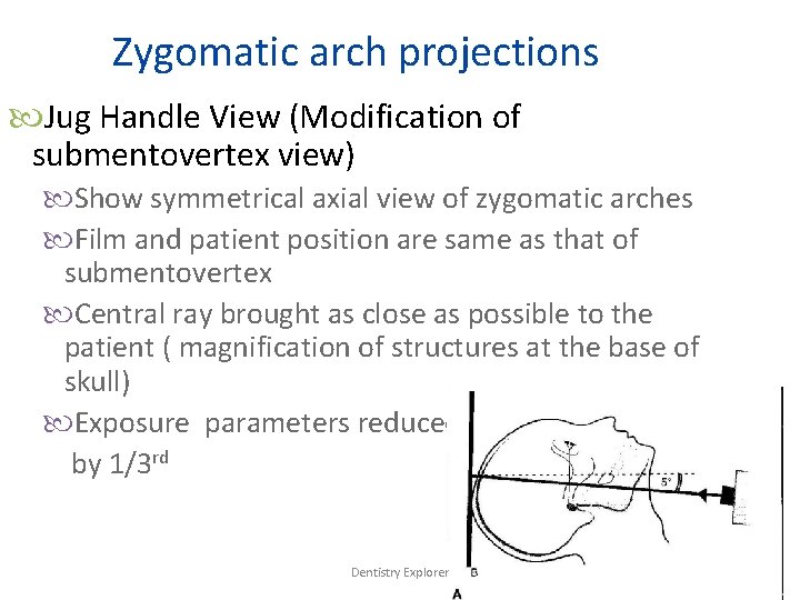
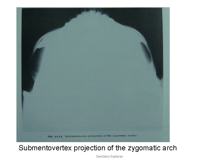
Zygomatic arch projections Jug Handle View (Modification of submentovertex view) Show symmetrical axial view of zygomatic arches Film and patient position are same as that of submentovertex Central ray brought as close as possible to the patient ( magnification of structures at the base of skull) Exposure parameters reduced by 1/3 rd Dentistry Explorer
Submentovertex projection of the zygomatic arch Dentistry Explorer
Radiography of temporomandibular joint Transcranial Transpharyngeal Transorbital Reverse towne’s Dentistry Explorer
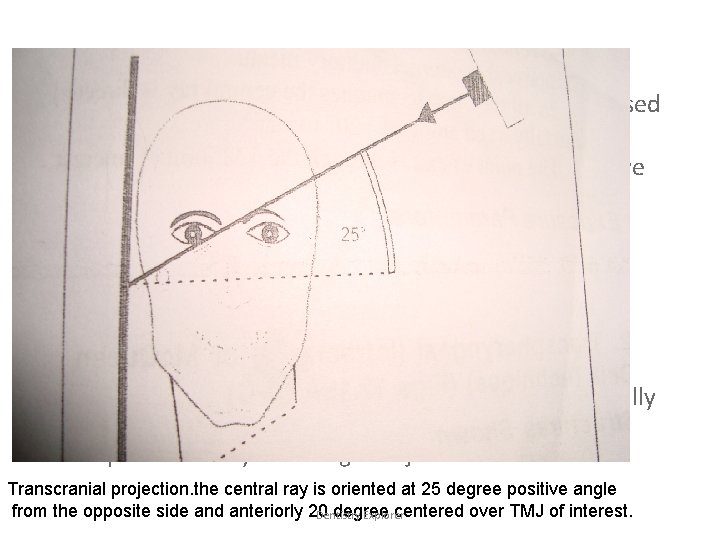
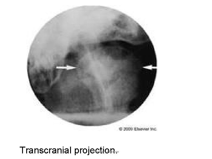
Transcranial projection stucture shown: Useful in detecting arthritic changes on the articular surface. Helps to evaluate the joints bony relationship Film position: The casettes is placed flat against the patients ear and center over the tm joint of interest, against the facial skin parallel to the saggital plane. Patient position: head is adjusted so that the saggital plane is vertical Ala tragal line is parallel to the floor. This view is taken with patient mouth in three position Open mouth Rest position Closed mouth Dentistry Explorer
Central ray: Point of entry is different according to technique used Post aural technique: Point of entry ofcentral ray is ½” behind and 2”above the auditory meatus Grewcock approach: the central ray enters through a point 2” above the external auditory meatus. Gills approach: the central rayenters throgh a point ½”anterior and 2”abovethe external auditory meatus. In all three technique the central ray is directed caudally at an angle of-20 to 25 degree The point of entry is through tm joint of interest. Transcranial projection. the central ray is oriented at 25 degree positive angle from the opposite side and anteriorly 20 degree centered over TMJ of interest. Dentistry Explorer
Transcranial projection. Dentistry Explorer
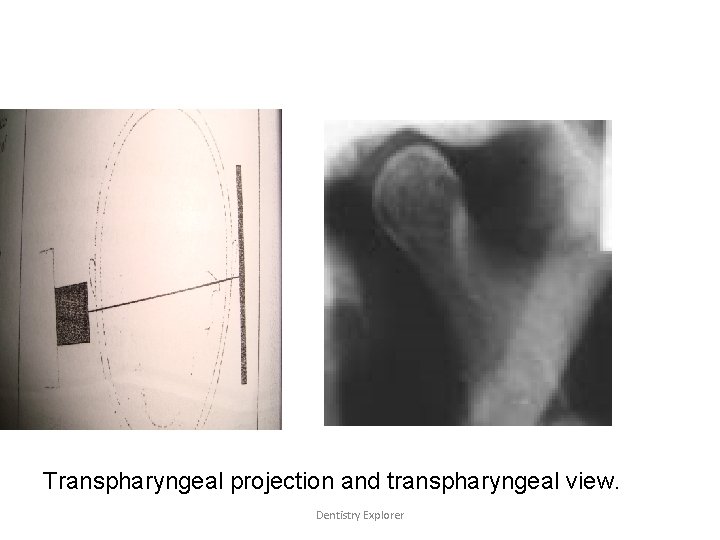
• Transpharyngeal: • Structure shown: – Lateral projection of condylar head and neck usually in mouth open position. • Film placement: – Cassette isplaced flat against the patient’s ear and is centered to a point 1/2”anterior to the external auditory meatus over the tm joint of interest, against facial skin parellel to the saggital plane. Dentistry Explorer
• Position of the patient: – Saggittal plane is vertical and parellel to the film, with the tm joint of inetrest adjacent to the film. – Film is centered to a point ½”anterior to the external auditory meatus. – Occlusal p lane shuld be parallel to the transverse axis of the film. – Patient is instucted to slowly inhale through the nose. – Patient should open his mouth so that the condyles move away from the base of the skulland the mandibular notch of the opposite side is enlarged. • Central ray: – Is directed from opposite sidecranially at an angle of 5 to 10 degree posteriorly through the mandibular notch to the tm joint of interest. Dentistry Explorer
Transpharyngeal projection and transpharyngeal view. Dentistry Explorer
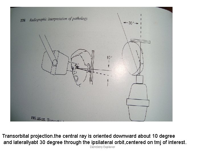
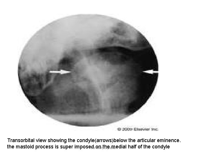
• Transorbital it is the conventionalfrontal tm joint projectionwhicg is most successful in dekineating the joint with minimal superimposition. • Stucture shown: – Articular surface and articular eminence. • Film position: – Behind the patient’s head at an angle of 45 degreeto the saggital plane. • Position of the patient: – Saggital plane is vertical. Dentistry Explorer
• Central ray: – Tube head is is placed infront of the patient’s face – Central ray is directed to the joint of interest. at an angle of-20 degree to srike the cassette at right angle. – Point of entry may be taken at • Pupil of the same eye. • Medial canthus of the opposite eye. Dentistry Explorer
Transorbital projection. the central ray is oriented downward about 10 degree and laterallyabt 30 degree through the ipsilateral orbit, centered on tmj of interest. Dentistry Explorer
Transorbital view showing the condyle(arrows)below the articular eminence. the mastoid process is super imposed on the medial half of the condyle Dentistry Explorer
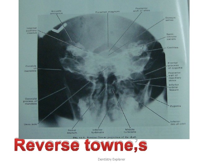
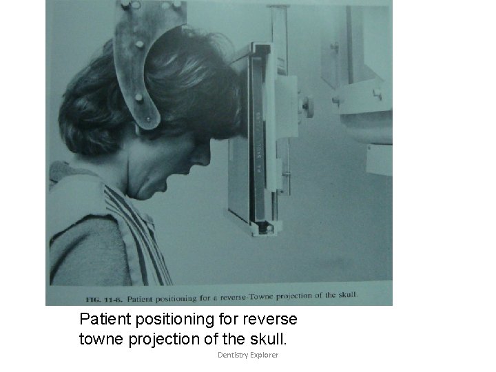
Reverse towne’s • Stucture shown: – This view is primarily meant for viewing the condylar neck and head. high fractures of condylar neck intra capsular fracture of the TMJ, quality of the articular surfaces, condylar hypoplasia and hypertrophy. • Film position: – Casette is placed perpendicular to the floor in a cassette holding device. the long axis of the cassette is placed vertically. Dentistry Explorer
• Position of the patient: – sagittal plane should be vertical and perpendicular to the film. – Film adjusted so that lips are centered to the film – Only patient’s forehead and tip of the nose should touch the film. – Patient is asked to keep his/her mouth wide open and the radiographic base line is at an angle of negative 30 degree to the film • Central ray: – Is directed through mid saggital planeat the Dentistry Explorer level of mandible, and is perpendicular to
Reverse towne’s Dentistry Explorer
Patient positioning for reverse towne projection of the skull. Dentistry Explorer
Skull projections • Lateral Cephalogram • True lateral view • PA Cephalogram • PA Skull • Towne’s view Dentistry Explorer
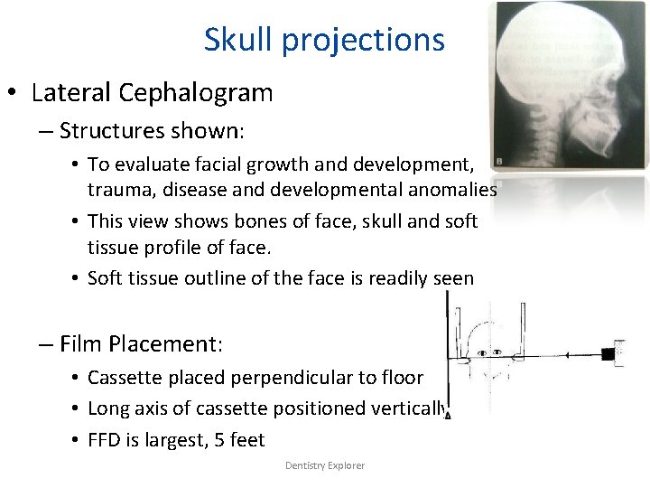
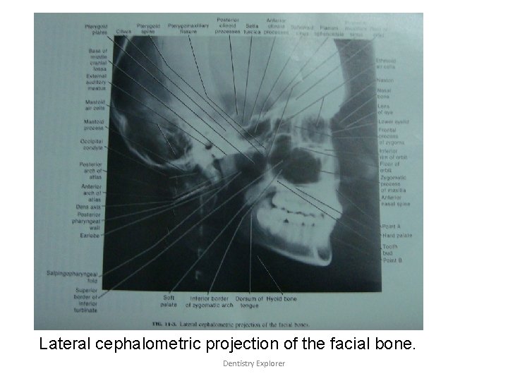
Skull projections • Lateral Cephalogram – Structures shown: • To evaluate facial growth and development, trauma, disease and developmental anomalies • This view shows bones of face, skull and soft tissue profile of face. • Soft tissue outline of the face is readily seen – Film Placement: • Cassette placed perpendicular to floor • Long axis of cassette positioned vertically • FFD is largest, 5 feet Dentistry Explorer
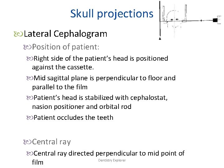
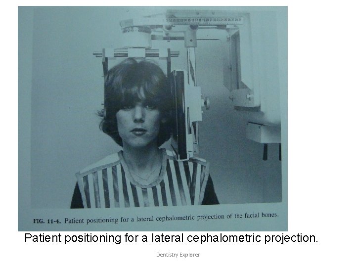
Skull projections Lateral Cephalogram Position of patient: Right side of the patient’s head is positioned against the cassette. Mid sagittal plane is perpendicular to floor and parallel to the film Patient’s head is stabilized with cephalostat, nasion positioner and orbital rod Patient occludes the teeth Central ray directed perpendicular to mid point of Dentistry Explorer film
Patient positioning for a lateral cephalometric projection. Dentistry Explorer
Lateral cephalometric projection of the facial bone. Dentistry Explorer
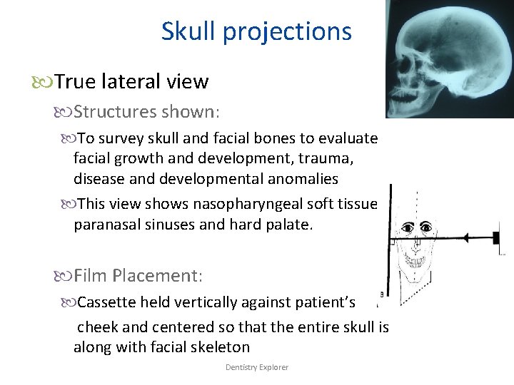
Skull projections True lateral view Structures shown: To survey skull and facial bones to evaluate facial growth and development, trauma, disease and developmental anomalies This view shows nasopharyngeal soft tissue, paranasal sinuses and hard palate. Film Placement: Cassette held vertically against patient’s cheek and centered so that the entire skull is along with facial skeleton Dentistry Explorer
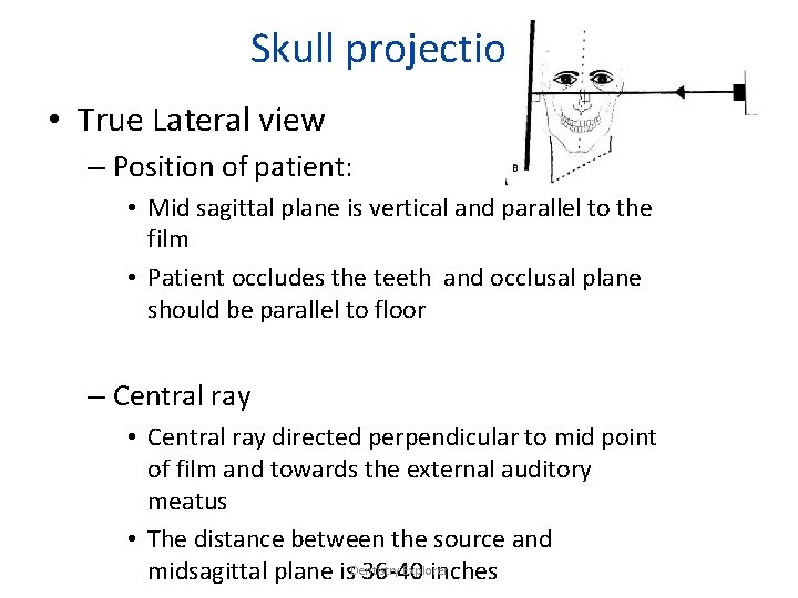
Skull projections • True Lateral view – Position of patient: • Mid sagittal plane is vertical and parallel to the film • Patient occludes the teeth and occlusal plane should be parallel to floor – Central ray • Central ray directed perpendicular to mid point of film and towards the external auditory meatus • The distance between the source and Explorer midsagittal plane is. Dentistry 36 -40 inches
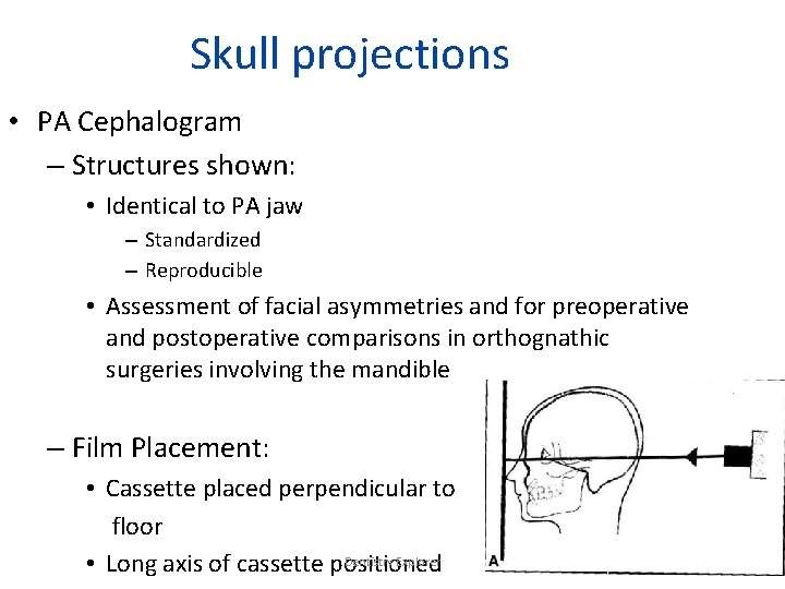
Skull projections • PA Cephalogram – Structures shown: • Identical to PA jaw – Standardized – Reproducible • Assessment of facial asymmetries and for preoperative and postoperative comparisons in orthognathic surgeries involving the mandible – Film Placement: • Cassette placed perpendicular to floor Dentistry Explorer • Long axis of cassette positioned
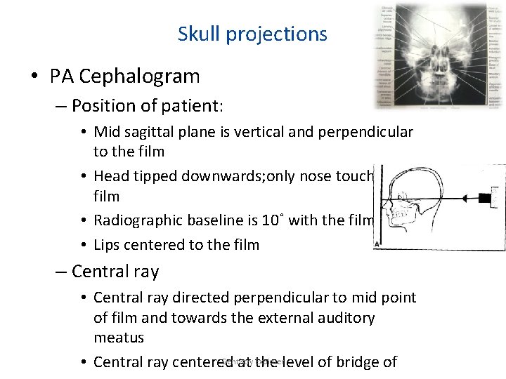
Skull projections • PA Cephalogram – Position of patient: • Mid sagittal plane is vertical and perpendicular to the film • Head tipped downwards; only nose touches the film • Radiographic baseline is 10˚ with the film • Lips centered to the film – Central ray • Central ray directed perpendicular to mid point of film and towards the external auditory meatus Dentistry Explorerlevel of bridge of • Central ray centered at the
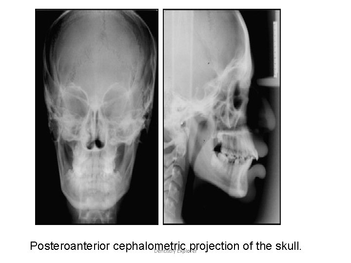
Posteroanterior cephalometric projection of the skull. Dentistry Explorer
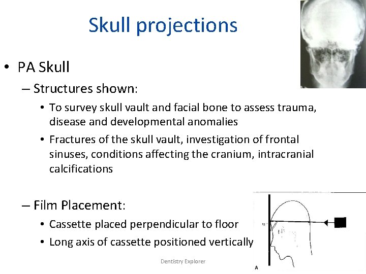
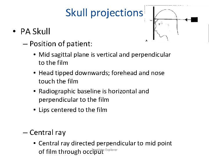
Skull projections • PA Skull – Structures shown: • To survey skull vault and facial bone to assess trauma, disease and developmental anomalies • Fractures of the skull vault, investigation of frontal sinuses, conditions affecting the cranium, intracranial calcifications – Film Placement: • Cassette placed perpendicular to floor • Long axis of cassette positioned vertically Dentistry Explorer
Skull projections • PA Skull – Position of patient: • Mid sagittal plane is vertical and perpendicular to the film • Head tipped downwards; forehead and nose touch the film • Radiographic baseline is horizontal and perpendicular to the film • Lips centered to the film – Central ray • Central ray directed perpendicular to mid point Dentistry Explorer of film through occiput
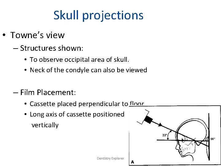
Skull projections • Towne’s view – Structures shown: • To observe occipital area of skull. • Neck of the condyle can also be viewed – Film Placement: • Cassette placed perpendicular to floor • Long axis of cassette positioned vertically Dentistry Explorer
Skull projections Towne’s view Position of patient: PA view, with the back of the head touching the film Canthomeatal line is perpendicular to film Patient occludes the teeth Central ray directed 30˚ to the canthomeatal line Passes through it at a point between the external auditory canals. Dentistry Explorer
References: • Karjodkar • White pharoah • Goaz. white • Internet sources Dentistry Explorer
Dentistry Explorer
? Dentistry Explorer
Thank you Dentistry Explorer