Exercise 10 The Omega network shown in Figure


- Slides: 9
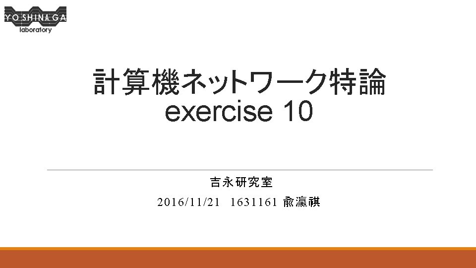
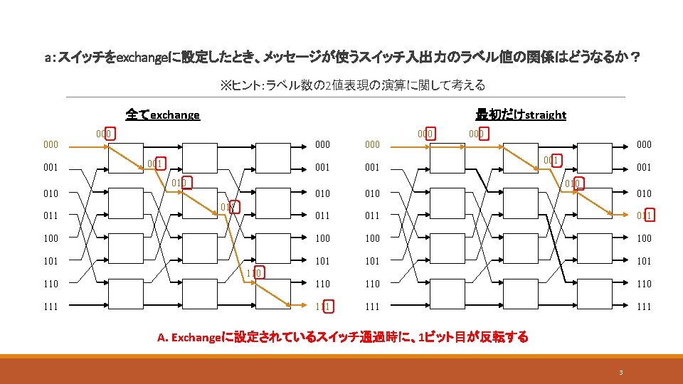
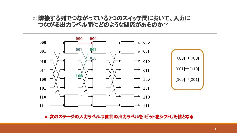
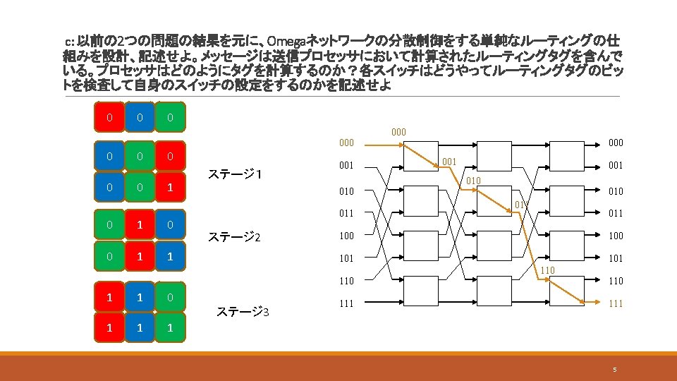
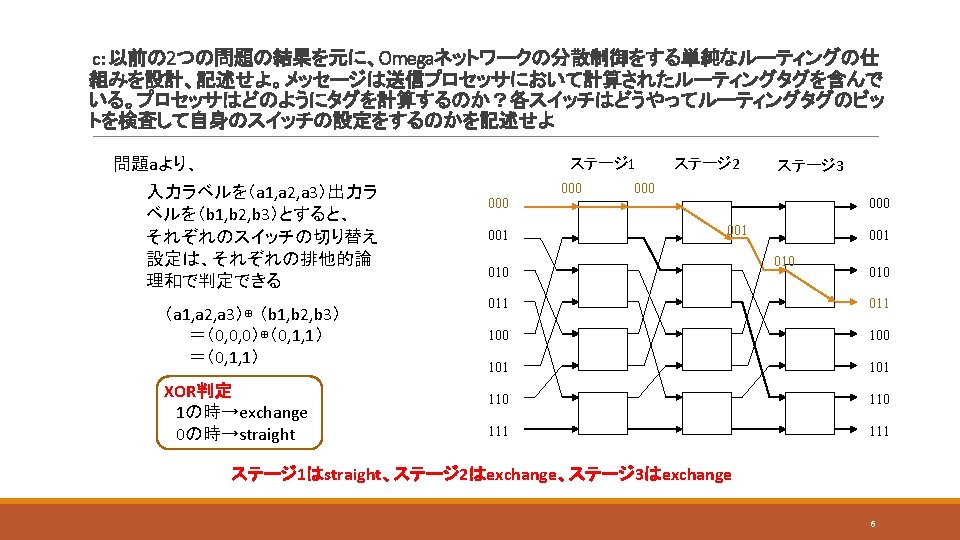
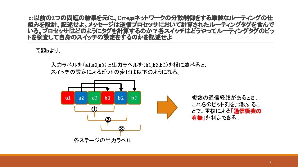
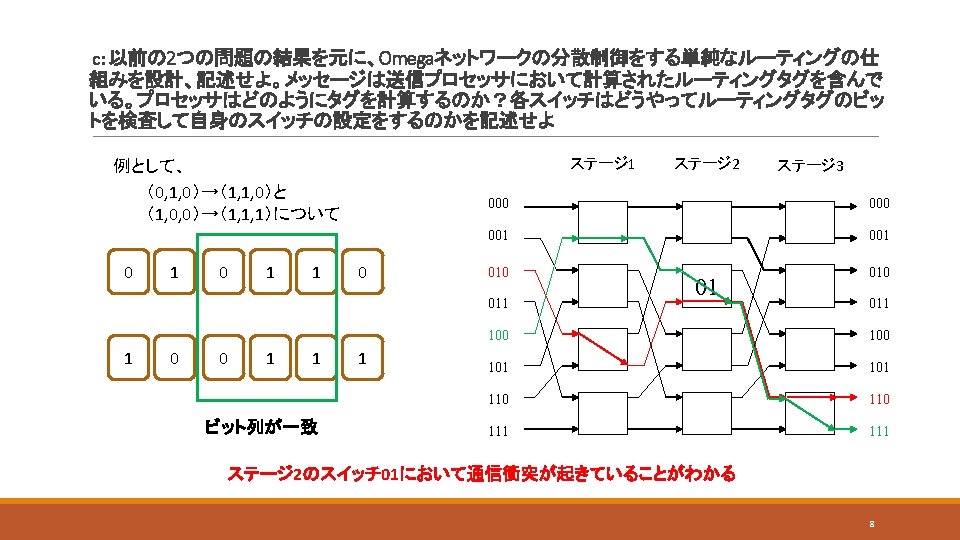
Exercise 10 The Omega network shown in Figure F. 11 on page F-31 consists of three columns of four switches, each with two inputs and two outputs. Each switch can be set to straight, which connects the upper switch input to the upper switch output and the lower input to the lower output, and to exchange, which connects the upper input to the lower output and vice versa for the lower input. For each column of switches, label the inputs and outputs 0, 1, . . . , 7 from top to bottom, to correspond with the numbering of the processors. 1
Exercise 10 straight exchange 2