EXAMPLE 2 PHOTODIODE A photodiode is a semiconductor


")


- Slides: 32
EXAMPLE 2 – PHOTODIODE A photodiode is a semiconductor device that converts light into current. The current is generated when photons are absorbed in the photodiode As for LED – Lights are emitted as a result of electrons recombine with holes. Circuit symbol for photodiode Operation: • A photon (light) of sufficient energy strikes the diode, it excites electrons – creating an electron-hole pairs. • If this process occurs near the depletion region, the electrons will be swept towards the negative terminal producing current flow • Photodiode is connected similar to reverse-biasing of a diode
I-V Characteristic of Photodiode Dark current refers to the leakage current produced by the diode although there is no light Photovoltaic mode; no biased Photoconductive mode Diode is reverse biased
Application of Photodiode • The detector is reverse biased to produce a linear response to the applied input light. • The amount of photocurrent generated is based upon the incident light and wavelength and can be viewed on an oscilloscope by attaching a load resistance on the output. • The function of the RC filter is to filter any high-frequency noise from the input supply that may contribute to a noisy output.
Basic Transimpedance Amplifier Also known as current to voltage converter – used when current has a more linear response compared to the voltage The feedback capacitor, Cf is used to improve the stability of the circuit. Vout = - I x RF (for low frequency signal - DC
Analogue and Digital Sensors Analogue Sensors produce a continuous output signal or voltage which is generally proportional to the quantity being measured. Examples: Temperature, Speed, Pressure, Displacement, Strain Characteristic: Continuous in nature For example, the temperature of a liquid can be measured using a thermometer or thermocouple which continuously responds to temperature changes as the liquid is heated up or cooled down. Very small signal (µV to m. V) range Amplification Analogue to Digital conversions
Digital Sensors produce a discrete digital output signals or voltages that are a digital representation of the quantity being measured. Digital sensors produce a Binary output signal in the form of a logic “ 1” or a logic “ 0”, (“ON” or “OFF”). For example, digital temperature sensor, DS 1620 • • • provides temperature of device with 9 -bit temperature readings. • temperature of the device is less than or equal to user defined temperature, TL then the TLOW is driven high. • If the temperature of the device exceeds TH and remains high until it falls below that of TL, then the TCOM is driven high. thermostat with its three thermal alarm outputs. temperature of device is greater than or equal to user defined temperature, TH then THIGH is driven high.
SIGNAL CONDITIONING Noisy
Key Functions of Signal Conditioning: q Amplification q Filter q Isolation q Attenuation q Linearization
AMPLIFICATION • Many sensors develop extremely low-level output signals • Two common examples of low-level sensors are thermocouples and strain-gauge (less than 50 m. V) • Requires amplification • Using Operational Amplifier (Op-Amp) • • Inverting Amplifier Non-Inverting Amplifier Differential Amplifier Instrumentation Amplifier
INVERTING AND NON-INVERTING AMPLIFIERS NOTE: The maximum input signal that the amplifier can handle without damage is usually about 2 V less than the supply voltage. For example, when the supply is ± 15 VDC, the input signal should not exceed ± 13 VDC.
Gain = -10 Vo = - 5 V Gain = 11 Vo = 5. 5 V
DIFFERENTIAL AMPLIFIERS • Differential-input amplifiers offer some advantages over inverting and noninverting amplifiers. • The output signal of the differential input amplifier responds only to the differential voltage that exists between the two input terminals. • Example to use differential amplifier is when thermocouple is used. In this figure, the gain is unity. But, we can make it the gain to be equal to 10 by making Rf to be 10 times larger than Ri But both Rf must be equal and both Ri must also be equal
For a gain of 10, where: Rf = 100 kΩ and Ri = 10 kΩ i. Prove that the output equation, Vo = 10 (V 1 – V 2) ii. What is the output voltage if the voltage difference is 50 m. V
INSTRUMENTATION AMPLIFIERS VA I = R 3 / R 2 ( VB – VA) I Vout = (V 2 - V 1) [2(R 1 / Rgain ) + 1 )](R 3 / R 2) I VB DIFFERENTIAL AMPLIFIER • ideal for measuring low-level signals in noisy environments without error, and amplifying small signals • the gain increases even more than just using differential amplifier • Using a potentiometer can vary the gain
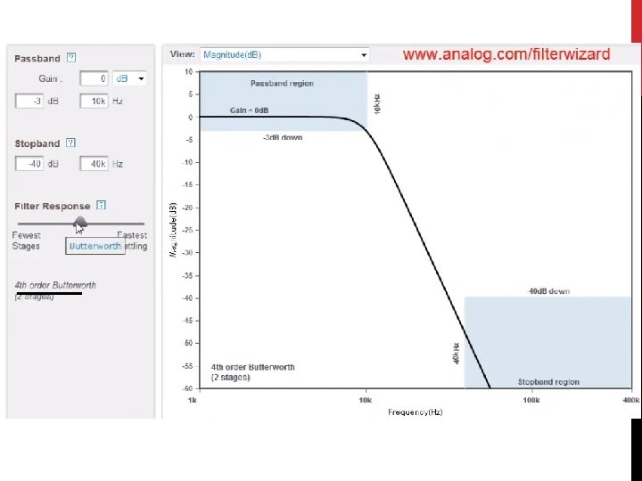
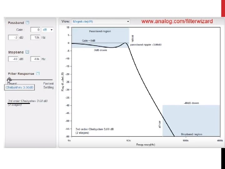
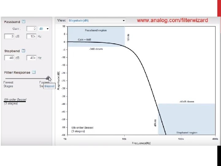
FILTERING • The three most common types of filters are called • Butterworth • • • fairly flat response in the pass-band a steep attenuation rate, a non-linear phase response • Chebyshev • • steeper rate of attenuation, develop some ripple in the pass band. The phase response is much more non-linear than the Butterworth. • Bessel • have the best step response and phase linearity. But requires a number of stages or orders
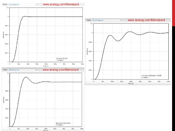
BESSEL Better step response in time domain, less ripple BUTTERWORTH Sharper frequency cutoff CHEBYSHEV Step response in time domain shows the characteristic of the system for the output to go from 0 – 1 at the point of the cutoff frequency
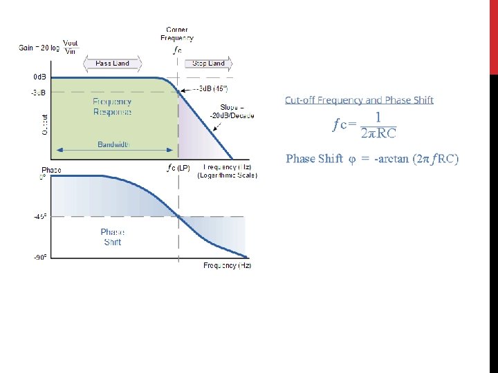
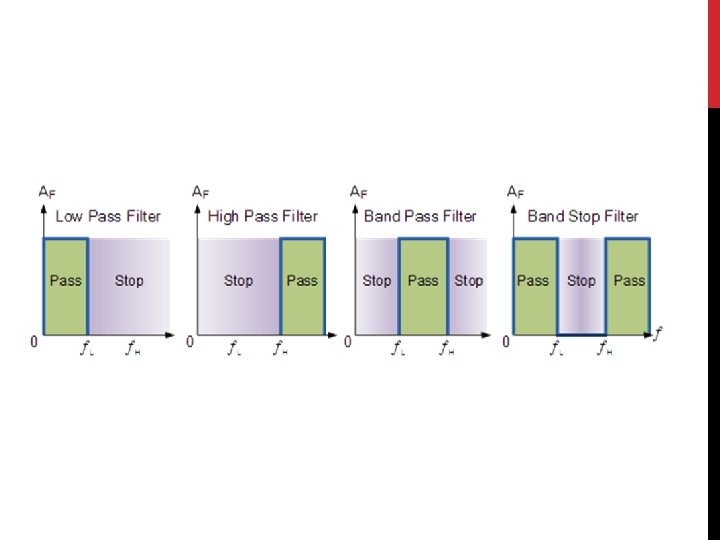
LOW-PASS FILTER A low-pass filter allows for easy passage of low-frequency signals from source to load, and difficult passage of high-frequency signals. The cutoff frequency for a low-pass filter is that frequency at which the output (load) voltage equals 70. 7% of the input (source) voltage. Above the cutoff frequency, the output voltage is lower than 70. 7% of the input, and vice versa. First order low pass filter
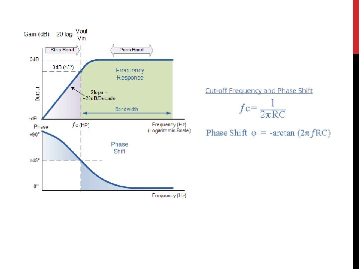
HIGH-PASS FILTER A high-pass filter allows for easy passage of high-frequency signals from source to load, and difficult passage of low-frequency signals. The cutoff frequency for a high-pass filter is that frequency at which the output (load) voltage equals 70. 7% of the input (source) voltage. Above the cutoff frequency, the output voltage is greater than 70. 7% of the input, and vice versa. First order high pass filter
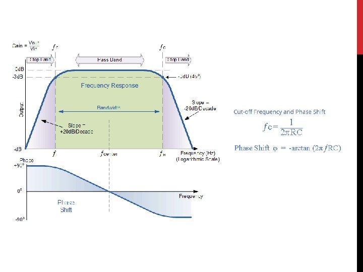
BAND-PASS FILTER • By connecting or “cascading” together a single Low Pass Filter circuit with a High Pass Filter circuit, we can produce another type of passive RC filter that passes a selected range or “band” of frequencies that can be either narrow or wide while attenuating all those outside of this range. • known commonly as a Band Pass Filter To set the first band pass frequency To set the second band pass frequency
EXAMPLE 1 A second-order band pass filter is to be constructed using RC components that will only allow a range of frequencies to pass above 1 k. Hz (1, 000 Hz) and below 30 k. Hz (30, 000 Hz). Assuming that both the resistors have values of 10 kΩ´s, calculate the values of the two capacitors required Answers: C 1 = 530 p. F C 2 = 15. 8 n. F
BAND-STOP FILTER • combine the low and high pass filter to produce another kind of RC filter network • that can block or at least severely attenuate a band of frequencies within these two cut-off frequency points.
• Band-pass filters are constructed by combining a low pass filter in series with a high pass filter • Band stop filters are created by combining together the low pass and high pass filter sections in a “parallel” type configuration as shown. Cutoff frequency is 200 Hz Cutoff frequency is 800 Hz
The band stop filter can be configured using 2 op-amps as non-inverting amplifiers (voltage followers) and their outputs are then connected using the summing amplifier configuration QUESTION: Can this configuration be used to create a band-pass filter instead?