
EXAMPLE 10 1 OBJECTIVE To determine the excess
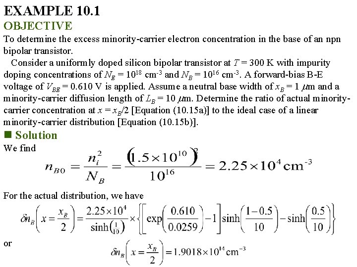
EXAMPLE 10. 1 OBJECTIVE To determine the excess minority-carrier electron concentration in the base of an npn bipolar transistor. Consider a uniformly doped silicon bipolar transistor at T = 300 K with impurity doping concentrations of NE = 1018 cm-3 and NB = 1016 cm-3. A forward-bias B-E voltage of VBE = 0. 610 V is applied. Assume a neutral base width of x. B = 1 m and a minority-carrier diffusion length of LB = 10 m. Determine the ratio of actual minoritycarrier concentration at x = x. B/2 [Equation (10. 15 a)] to the ideal case of a linear minority-carrier distribution [Equation (10. 15 b)]. n Solution We find For the actual distribution, we have or
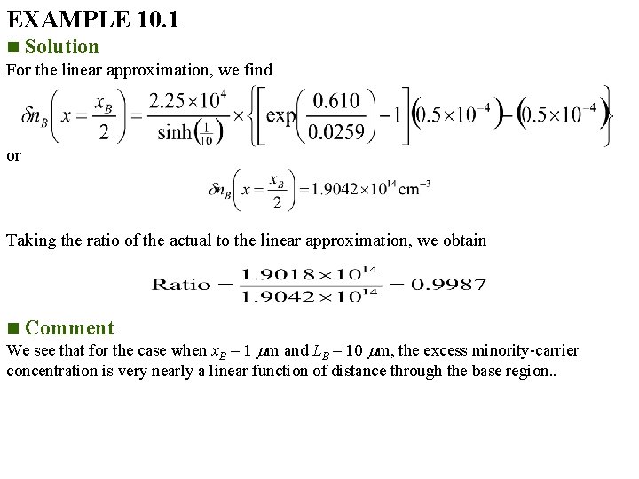
EXAMPLE 10. 1 n Solution For the linear approximation, we find or Taking the ratio of the actual to the linear approximation, we obtain n Comment We see that for the case when x. B = 1 m and LB = 10 m, the excess minority-carrier concentration is very nearly a linear function of distance through the base region. .
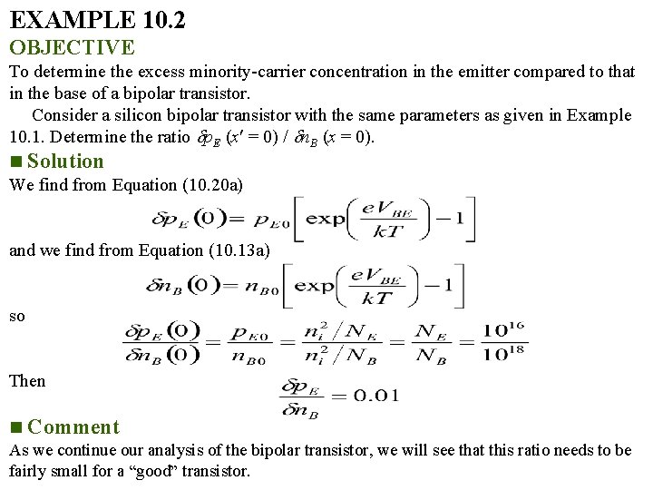
EXAMPLE 10. 2 OBJECTIVE To determine the excess minority-carrier concentration in the emitter compared to that in the base of a bipolar transistor. Consider a silicon bipolar transistor with the same parameters as given in Example 10. 1. Determine the ratio p. E (x = 0) / n. B (x = 0). n Solution We find from Equation (10. 20 a) and we find from Equation (10. 13 a) so Then n Comment As we continue our analysis of the bipolar transistor, we will see that this ratio needs to be fairly small for a “good” transistor.
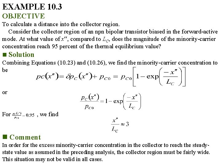
EXAMPLE 10. 3 OBJECTIVE To calculate a distance into the collector region. Consider the collector region of an npn bipolar transistor biased in the forward-active mode. At what value of x , compared to LC, does the magnitude of the minority-carrier concentration reach 95 percent of thermal equilibrium value? n Solution Combining Equations (10. 23) and (10. 26), we find the minority-carrier concentration to be or For , we find n Comment In order for the excess minority-carrier concentration in the collector to reach the steadystate value as assumed in the preceding analysis, the collector region must be fairly wide. This situation may not be valid in all cases.
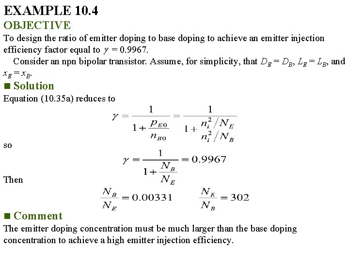
EXAMPLE 10. 4 OBJECTIVE To design the ratio of emitter doping to base doping to achieve an emitter injection efficiency factor equal to = 0. 9967. Consider an npn bipolar transistor. Assume, for simplicity, that DE = DB, LE = LB, and x. E = x. B. n Solution Equation (10. 35 a) reduces to so Then n Comment The emitter doping concentration must be much larger than the base doping concentration to achieve a high emitter injection efficiency.
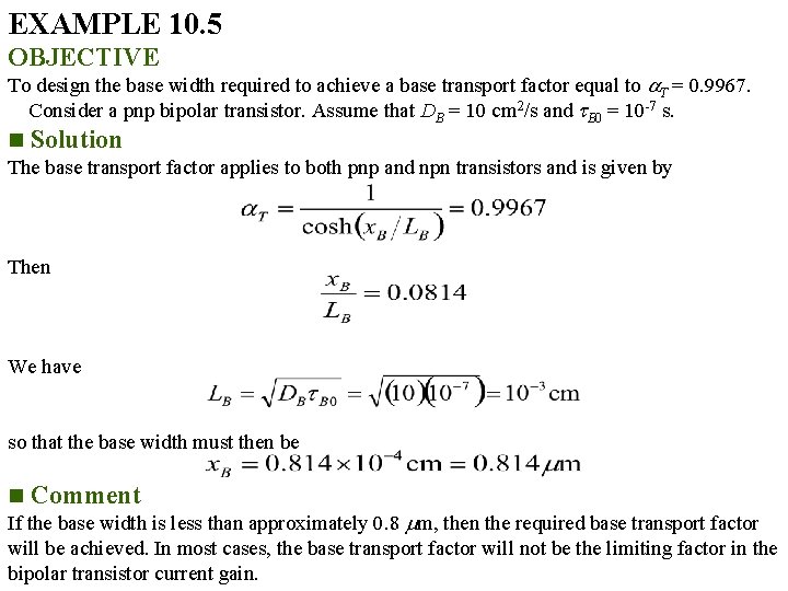
EXAMPLE 10. 5 OBJECTIVE To design the base width required to achieve a base transport factor equal to T = 0. 9967. Consider a pnp bipolar transistor. Assume that DB = 10 cm 2/s and B 0 = 10 -7 s. n Solution The base transport factor applies to both pnp and npn transistors and is given by Then We have so that the base width must then be n Comment If the base width is less than approximately 0. 8 m, then the required base transport factor will be achieved. In most cases, the base transport factor will not be the limiting factor in the bipolar transistor current gain.
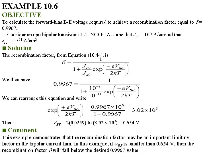
EXAMPLE 10. 6 OBJECTIVE To calculate the forward-bias B-E voltage required to achieve a recombination factor equal to = 0. 9967. Consider an npn bipolar transistor at T = 300 K. Assume that Jr 0 = 10 -8 A/cm 2 ad that Js 0 = 10 -11 A/cm 2. n Solution The recombination factor, from Equation (10. 44), is We then have We can rearrange this equation and write Then n Comment VBE = 2(0. 0259) ln (3. 02 105) = 0. 654 V This example demonstrates that the recombination factor may be an important limiting factor in the bipolar current fain. In this example, if VBE is smaller than 0. 654 V, then the recombination factor will fall below the desired 0. 9967 value.
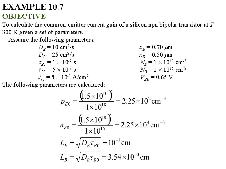
EXAMPLE 10. 7 OBJECTIVE To calculate the common-emitter current gain of a silicon npn bipolar transistor at T = 300 K given a set of parameters. Assume the following parameters: DE = 10 cm 2/s x. B = 0. 70 m DB = 25 cm 2/s x. E = 0. 50 m E 0 = 1 10 -7 s NE = 1 1018 cm-3 B 0 = 5 10 -7 s NB = 1 1016 cm-3 Jr 0 = 5 10 -8 A/cm 2 VBE = 0. 65 V The following parameters are calculated:
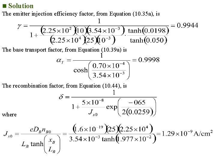
n Solution The emitter injection efficiency factor, from Equation (10. 35 a), is The base transport factor, from Equation (10. 39 a) is The recombination factor, from Equation (10. 44), is where
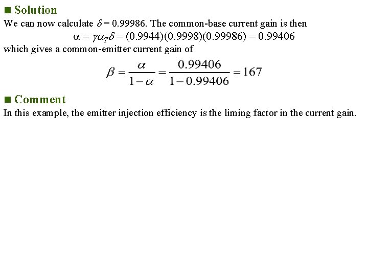
n Solution We can now calculate = 0. 99986. The common-base current gain is then = T = (0. 9944)(0. 99986) = 0. 99406 which gives a common-emitter current gain of n Comment In this example, the emitter injection efficiency is the liming factor in the current gain.
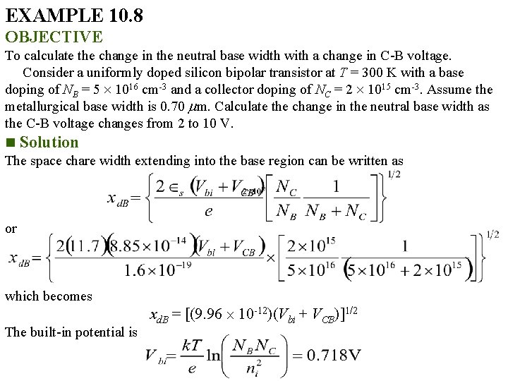
EXAMPLE 10. 8 OBJECTIVE To calculate the change in the neutral base width with a change in C-B voltage. Consider a uniformly doped silicon bipolar transistor at T = 300 K with a base doping of NB = 5 1016 cm-3 and a collector doping of NC = 2 1015 cm-3. Assume the metallurgical base width is 0. 70 m. Calculate the change in the neutral base width as the C-B voltage changes from 2 to 10 V. n Solution The space chare width extending into the base region can be written as or which becomes The built-in potential is xd. B = [(9. 96 10 -12)(Vbi + VCB)]1/2
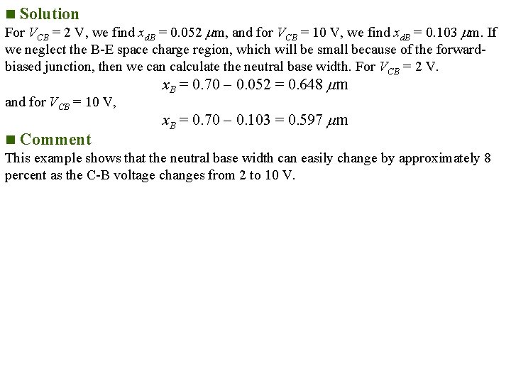
n Solution For VCB = 2 V, we find xd. B = 0. 052 m, and for VCB = 10 V, we find xd. B = 0. 103 m. If we neglect the B-E space charge region, which will be small because of the forwardbiased junction, then we can calculate the neutral base width. For VCB = 2 V. and for VCB = 10 V, x. B = 0. 70 0. 052 = 0. 648 m x. B = 0. 70 0. 103 = 0. 597 m n Comment This example shows that the neutral base width can easily change by approximately 8 percent as the C-B voltage changes from 2 to 10 V.
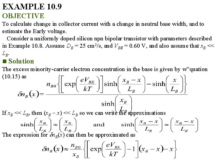
EXAMPLE 10. 9 OBJECTIVE To calculate change in collector current with a change in neutral base width, and to estimate the Early voltage. Consider a uniformly doped silicon npn bipolar transistor with parameters described in Example 10. 8. Assume DB = 25 cm 2/s, and VBE = 0. 60 V, and also assume that x. B << LB. n Solution The excess minority-carrier electron concentration in the base is given by w”quation (10. 15) as If x. B << LB, then (x. B x) << LB so we can write the approximations The expression for n. B(x) can then be approximated as
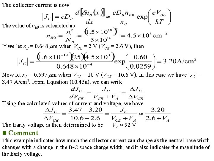
The collector current is now The value of n. B 0 is calculated as If we let x. B = 0. 648 m when VCB = 2 V (VCE = 2. 6 V), then Now let x. B = 0. 597 m when VCB = 10 V (VCE = 10. 6 V). In this case we have |JC| = 3. 47 A/cm 2. From Equation (10. 45 a), we can write Using the calculated values of current and voltage, we have The Early voltage is then determined to be n Comment VA 92 V This example indicates how much the collector current can change as the neutral base width changes with a change in the B-C space charge width, and it also indicates the magnitude of the Early voltage.
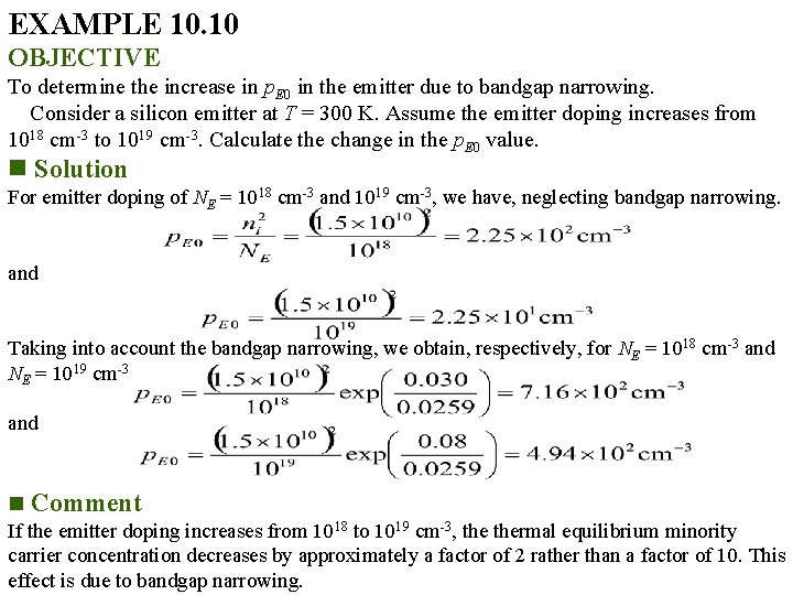
EXAMPLE 10. 10 OBJECTIVE To determine the increase in p. E 0 in the emitter due to bandgap narrowing. Consider a silicon emitter at T = 300 K. Assume the emitter doping increases from 1018 cm-3 to 1019 cm-3. Calculate the change in the p. E 0 value. n Solution For emitter doping of NE = 1018 cm-3 and 1019 cm-3, we have, neglecting bandgap narrowing. and Taking into account the bandgap narrowing, we obtain, respectively, for NE = 1018 cm-3 and NE = 1019 cm-3 and n Comment If the emitter doping increases from 1018 to 1019 cm-3, thermal equilibrium minority carrier concentration decreases by approximately a factor of 2 rather than a factor of 10. This effect is due to bandgap narrowing.
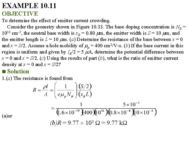
EXAMPLE 10. 11 OBJECTIVE To determine the effect of emitter current crowding. Consider the geometry shown in Figure 10. 33. The base doping concentration is NB = 1016 cm-3, the neutral base width is x. B = 0. 80 m, the emitter width is S = 10 m, and the emitter length is L = 10 m. (a) Determine the resistance of the base between x = 0 and x = S/2. Assume a hole mobility of p = 400 cm 2/V-s. (b) If the base current in this region is uniform and given by IB/2 = 5 A, determine the potential difference between x = 0 and x = S/2. (c) Using the results of part (b), what is the ratio of emitter current density at x = 0 and x = S/2? n Solution 1. (a) The resistance is found from (a)or (b)R = 9. 77 103 = 9. 77 k
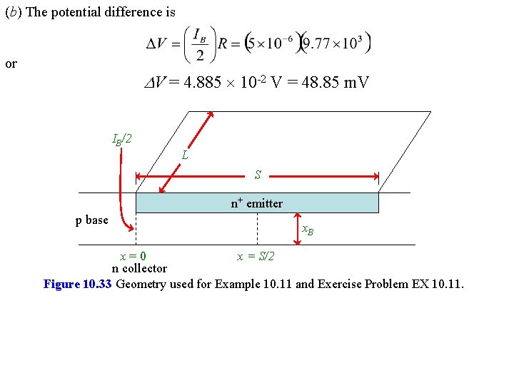
(b) The potential difference is or V = 4. 885 10 -2 V = 48. 85 m. V IB/2 L S n+ emitter p base x. B x=0 x = S/2 n collector Figure 10. 33 Geometry used for Example 10. 11 and Exercise Problem EX 10. 11.
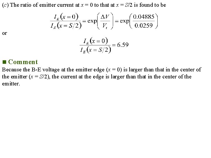
(c) The ratio of emitter current at x = 0 to that at x = S/2 is found to be or n Comment Because the B-E voltage at the emitter edge (x = 0) is larger than that in the center of the emitter (x = S/2), the current at the edge is larger than that in the center of the emitter.
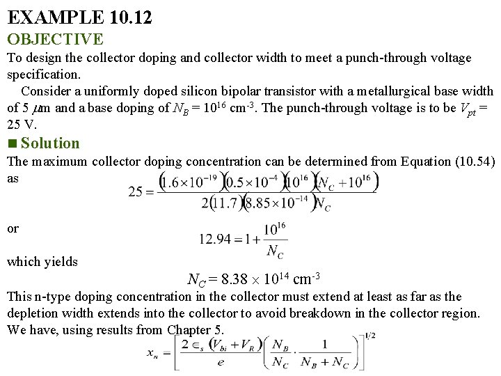
EXAMPLE 10. 12 OBJECTIVE To design the collector doping and collector width to meet a punch-through voltage specification. Consider a uniformly doped silicon bipolar transistor with a metallurgical base width of 5 m and a base doping of NB = 1016 cm-3. The punch-through voltage is to be Vpt = 25 V. n Solution The maximum collector doping concentration can be determined from Equation (10. 54) as or which yields NC = 8. 38 1014 cm-3 This n-type doping concentration in the collector must extend at least as far as the depletion width extends into the collector to avoid breakdown in the collector region. We have, using results from Chapter 5.
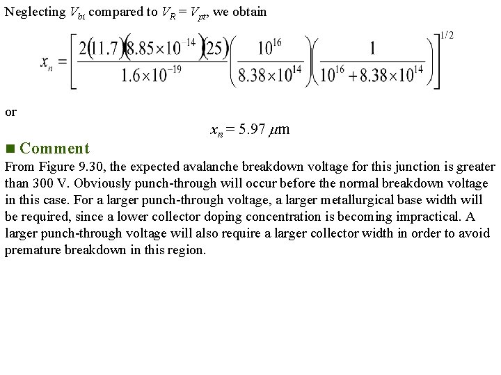
Neglecting Vbi compared to VR = Vpt, we obtain or xn = 5. 97 m n Comment From Figure 9. 30, the expected avalanche breakdown voltage for this junction is greater than 300 V. Obviously punch-through will occur before the normal breakdown voltage in this case. For a larger punch-through voltage, a larger metallurgical base width will be required, since a lower collector doping concentration is becoming impractical. A larger punch-through voltage will also require a larger collector width in order to avoid premature breakdown in this region.
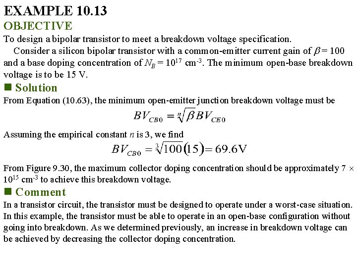
EXAMPLE 10. 13 OBJECTIVE To design a bipolar transistor to meet a breakdown voltage specification. Consider a silicon bipolar transistor with a common-emitter current gain of = 100 and a base doping concentration of NB = 1017 cm-3. The minimum open-base breakdown voltage is to be 15 V. n Solution From Equation (10. 63), the minimum open-emitter junction breakdown voltage must be Assuming the empirical constant n is 3, we find From Figure 9. 30, the maximum collector doping concentration should be approximately 7 1015 cm-3 to achieve this breakdown voltage. n Comment In a transistor circuit, the transistor must be designed to operate under a worst-case situation. In this example, the transistor must be able to operate in an open-base configuration without going into breakdown. As we determined previously, an increase in breakdown voltage can be achieved by decreasing the collector doping concentration.
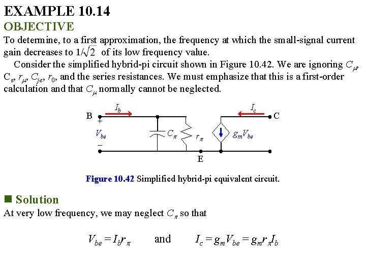
EXAMPLE 10. 14 OBJECTIVE To determine, to a first approximation, the frequency at which the small-signal current gain decreases to 1/ of its low frequency value. Consider the simplified hybrid-pi circuit shown in Figure 10. 42. We are ignoring C , Cs, r , Cje, r 0, and the series resistances. We must emphasize that this is a first-order calculation and that C normally cannot be neglected. B Ib + Vbe Ic C r C gm. Vbe E Figure 10. 42 Simplified hybrid-pi equivalent circuit. n Solution At very low frequency, we may neglect C so that Vbe = Ibr and Ic = gm. Vbe = gmr Ib
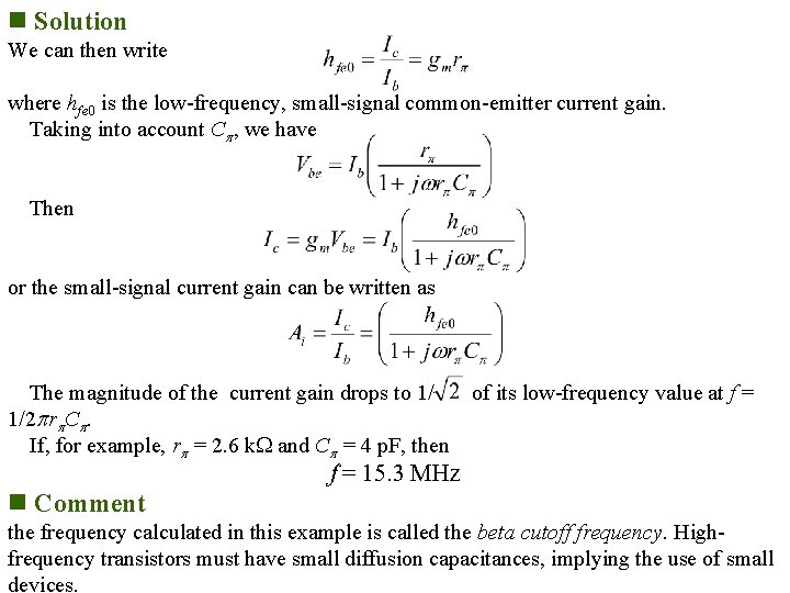
n Solution We can then write where hfe 0 is the low-frequency, small-signal common-emitter current gain. Taking into account C , we have Then or the small-signal current gain can be written as The magnitude of the current gain drops to 1/ 1/2 r C. If, for example, r = 2. 6 k and C = 4 p. F, then of its low-frequency value at f = 15. 3 MHz n Comment the frequency calculated in this example is called the beta cutoff frequency. Highfrequency transistors must have small diffusion capacitances, implying the use of small devices.
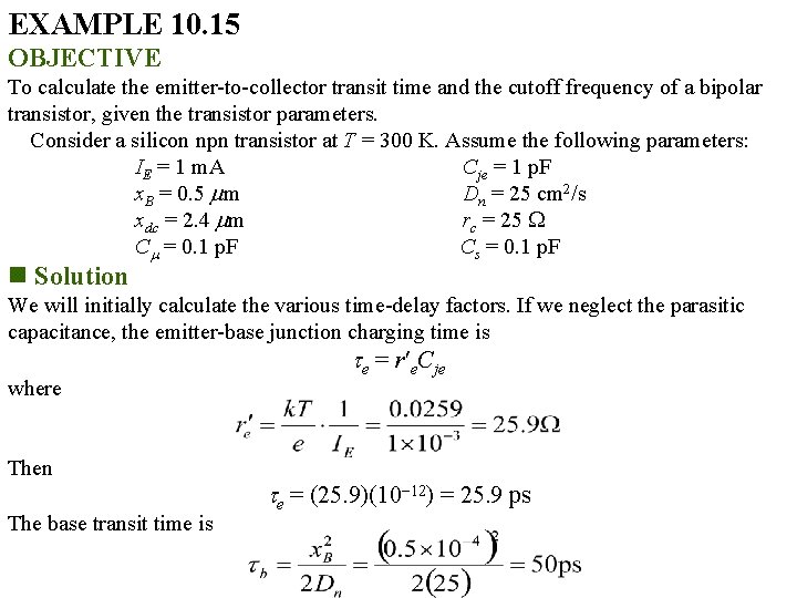
EXAMPLE 10. 15 OBJECTIVE To calculate the emitter-to-collector transit time and the cutoff frequency of a bipolar transistor, given the transistor parameters. Consider a silicon npn transistor at T = 300 K. Assume the following parameters: IE = 1 m. A Cje = 1 p. F x. B = 0. 5 m Dn = 25 cm 2/s xdc = 2. 4 m rc = 25 C = 0. 1 p. F Cs = 0. 1 p. F n Solution We will initially calculate the various time-delay factors. If we neglect the parasitic capacitance, the emitter-base junction charging time is where Then The base transit time is e = r e. Cje e = (25. 9)(10 12) = 25. 9 ps
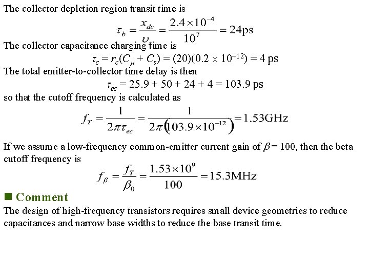
The collector depletion region transit time is The collector capacitance charging time is c = rc(C + Cs) = (20)(0. 2 10 12) = 4 ps The total emitter-to-collector time delay is then ec = 25. 9 + 50 + 24 + 4 = 103. 9 ps so that the cutoff frequency is calculated as If we assume a low-frequency common-emitter current gain of = 100, then the beta cutoff frequency is n Comment The design of high-frequency transistors requires small device geometries to reduce capacitances and narrow base widths to reduce the base transit time.
- Slides: 25