Exact Zero Skew Clock Routing Prof John Reuben

Exact Zero Skew Clock Routing Prof. John Reuben, VIT University, INDIA
 +Cx. Ru + Cy(Ru+Rv)")
Elmore delay in a clock tree telmore, v=Cu. Ru+ Cv(Ru+Rv) +Cx. Ru + Cy(Ru+Rv) + Cz(Ru+Rv)
 +Cx. Ru + Cy(Ru+Rv) + Cz(Ru+Rv) t")
Elmore Delay t 0, v=Cu. Ru+ Cv(Ru+Rv) +Cx. Ru + Cy(Ru+Rv) + Cz(Ru+Rv) t 0, v =Ru(Cu +Cv+ Cx +Cy +Cz ) + Rv(Cv +Cy +Cz) t 0, u = Ru(Cu +Cv+ Cx +Cy +Cz ) tu, z = tu, v + t v, z tu, v = t 0, v - t 0, u = Rv(Cv +Cy +Cz) tu, z = Rv(Cv +Cy +Cz) + tv, z
 + tv, z")
tu, z = Rv(Cv +Cy +Cz) + tv, z

Basic Concept of zero skew merge process

Basic Concept of zero skew merge process

Algorithm • We assume every subtree has achieved zero skew, which means the signal delay from the root of the subtree to its leaf nodes are equal. • So we start with leaf nodes, which are subtress with zero skew(to start with) • To interconnect two zero-skewed subtrees with a wire and ensure zero skew of the merged tree, the problem to be solved is the decision of where on the wire the new root of the merged tree will be, such that the delay time from this new root to all leaf nodes are equal, i. e. , zero skew.

zero-skew-merge process x. l r 1 c 1/2 A c 1/2 t 1 C 1 Subtree 1 Tapping point (1 – x). l c 2/2 r 2 B c 2/2 t 2 C 2 Subtree 2

zero-skew-merge process To ensure the delay from the tapping point to leaf nodes of both subtrees being equal, it requires that Let α be the resistance per unit length of wire and β be the capacitance per unit length of wire.

If 0 < x < 1, the tapping point is somewhere along the segment interconnecting the two subtrees and is legal. In case that x < 0 or x > 1, it indicates the two subtrees are too much out of balance. The interconnection wire has to be elongated. For x < 0. For this case, the tapping point has to be exactly on the root of subtree 1 in order to minimize total interconnection length. If elongated wirelength is l’, then

Example

Merge A and B • Let B be sub-tree 1 and A be sub-tree 2 • Let resistance/unit length, α=0. 1 ohm, capacitance/unit length, β=0. 2 Farad • l=20 units • x=18/20 = 0. 6 • Distance from tapping point to subtree 1 (node B)=xl=12 units • Distance from tapping point to subtree 2(node A)=(1 -x)l=8 units • T. P of (A, B) pair is E(10, 6) • RC delay from E to node A= RC delay from E to node B
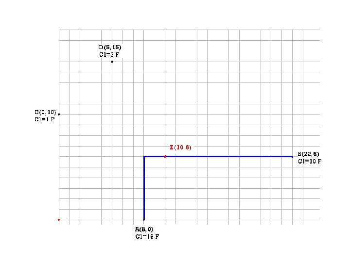

RC delay from E to node B = t 1= ? t 1= r 1(c 1/2 + C 1) t 1= αxl(βxl/2 + C 1) t 1=13. 44

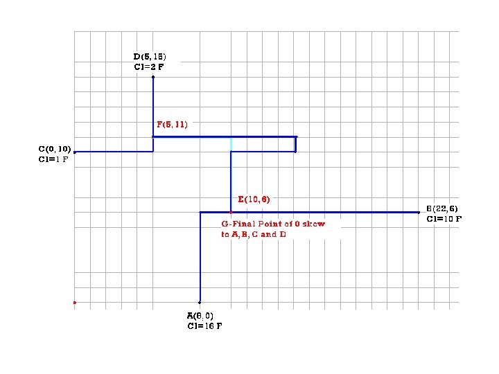
Merge C and D • • Let C be sub-tree 1 and D be sub-tree 2 l=10 units x=3/5 = 0. 6 Distance from tapping point to subtree 1 (node B)=xl=6 units Distance from tapping point to subtree 2(node A)=(1 -x)l=4 units T. P of (C, D) pair is F(5, 11) RC delay from F to node C= RC delay from F to node D=0. 96 units t 2=0. 96


Merge E and F • Let E be sub-tree 1 and F be sub-tree 2 • l=10 units • Capacitance at E =(node cap. of A) +(node cap. of B)+ (cap. Of wire joining A and B) = 30 F • Capacitance at F =(node cap. of C) +(node cap. of D)+ (cap. Of wire joining C and D) = 5 F • t 1=13. 44, t 2=0. 96 • x= -0. 175 , nodes E and F are heavily unbalanced. • So we have to make tapping point as root of subtree 1(node E) and elongate the wire • l’=18. 28 units • Original length between E and F is only 10 units. • We have to do snaking for 8. 28 units

Ren Song Tsay, “An Exact zero skew clock routing algorithm”, IEEE Transactions on CAD, February 1993
- Slides: 19