Ex five telemetry signals each of bandwidth 1

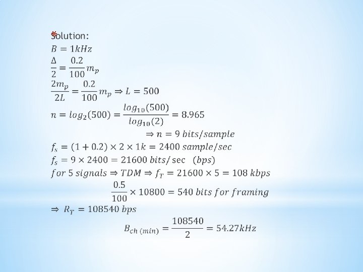
Ex: five telemetry signals, each of bandwidth 1 k. Hz are to be transmitted simultaneously by binary PCM. The maximum tolerable error in sample amplitude is 0. 2% of the peak signal amplitude. The signals must be sampled at least 20% above the Nyquist rate. Framing and synchronizing requires an additional 0. 5% extra bits. Determine the data rate of resulted signal to be transmitted and then minimum bandwidth required to transmit this signal.


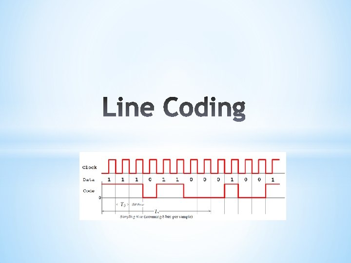
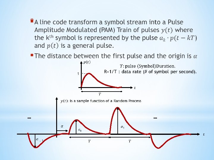
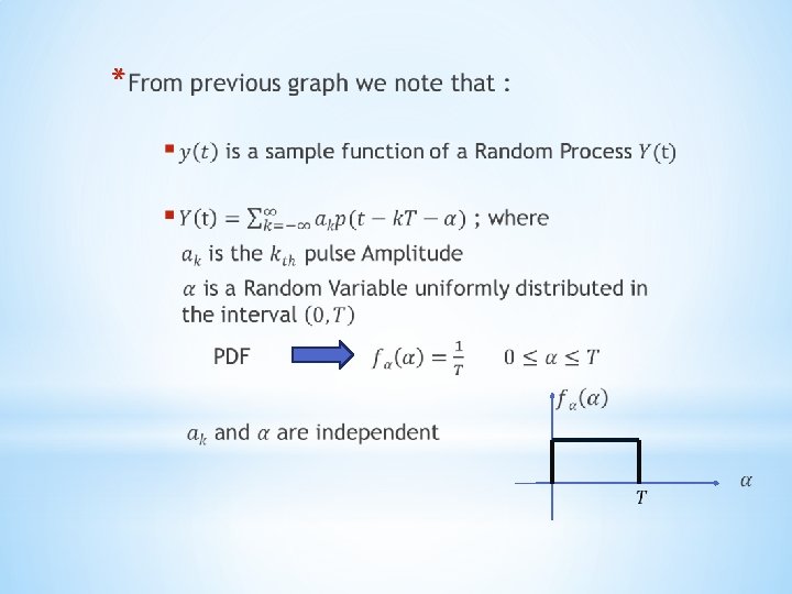
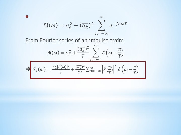
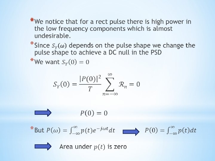
§ Line coding refers to the process of representing a symbol stream as electrical signals. *Some properties are desired in a line code such as: 1. 2. Low Transmission Bandwidth. 3. 4. Error Detection & Correction Capabilities e. g. Bipolar 5. Adequate Timing Content (Clock recovery): does the line code carry clock information ? Power Efficient : for a given Bandwidth and a specific detection error rate, the Transmitted Power should be as low as possible. Favorable Power Spectral Density (PSD) : it is desirable to get rid of low freq. components and DC shifts (codes that do this are called DC balanced, DC equalized, Zero-DC or Zero-Bias)

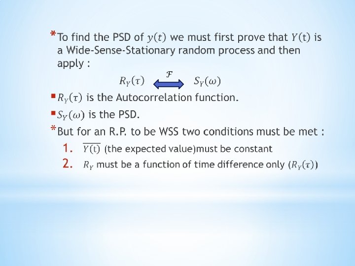
6. Transparency : A line code in which the bit pattern does not affect the accuracy of timing information is said to be Transparent. ØThe best way of analyzing a line code is to examine its PSD which gives valuable information about both power and bandwidth.
")
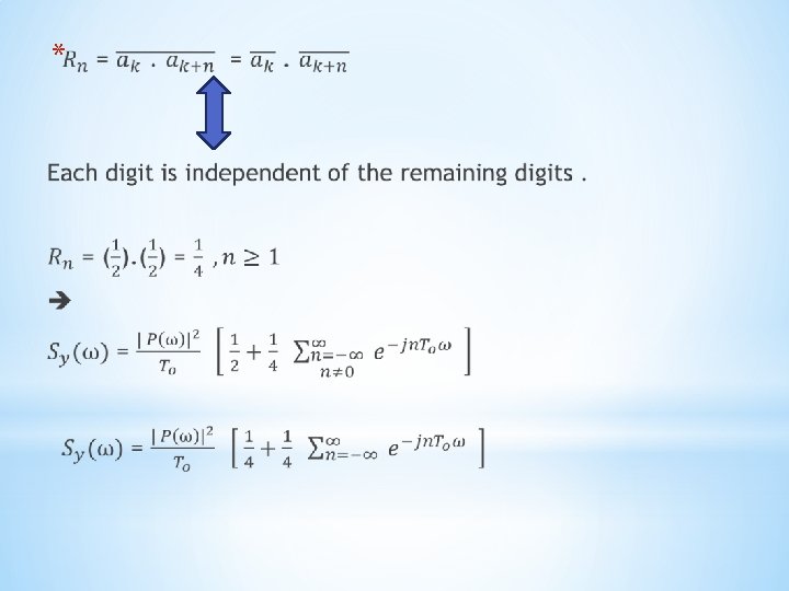
* Energy Spectral Density (ESD)

*The previous equation is a general equation for any line code. We now explore some of the popular Binary line code such as : 1. 2. 3. * Polar line code Unipolar line code ( on-off signaling) Bipolar line code (Alternate Mark Inversion)

* 1 1 1 0 1 1 To * 0 0 0 1

For polar line code * t

* EB

* EB
")
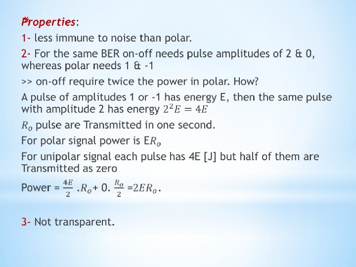
*Not Bandwidth Efficient *No Error Detection Or Correction *No DC value (DC = 0) *Most Power Efficient Line Code : for the same power it will result in the lowest Bit error rate (BER). *

* For RZ Pulses Timing Info can be extracted by Rectifying the polar signal which results in a periodic signal with clock freq. 1 1 1 0 1 1 To Rectifier 0 0 0 1

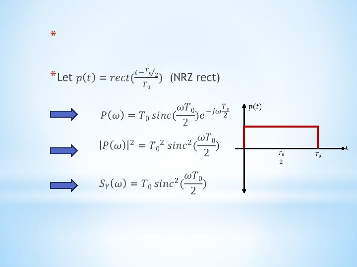
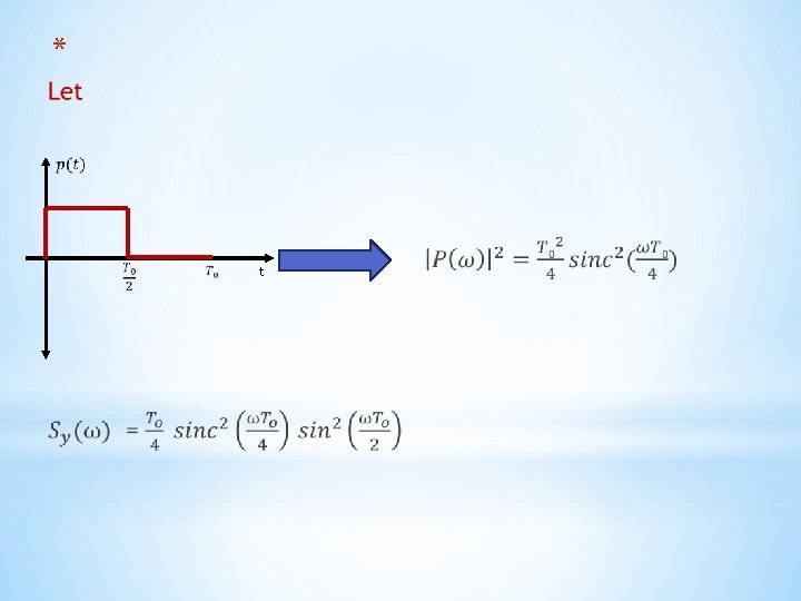
*One pulse shape that satisfies the previous requirement is : *If this pulse shape is used with polar line code, it is called Manchester , split phase or twinned Binary coding * t

*The PSD of Manchester coding is shown below it’s evident that low frequency components disappeared EB

 no signal")
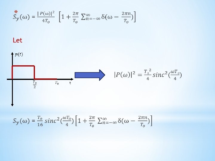
* p(t) no signal

* … … -2 To -To To 2 To 3 To t
 freq. EB")
* Discrete component of the data rate (clock) freq. EB

Explain this ? ! = Unipolar Polar + clock


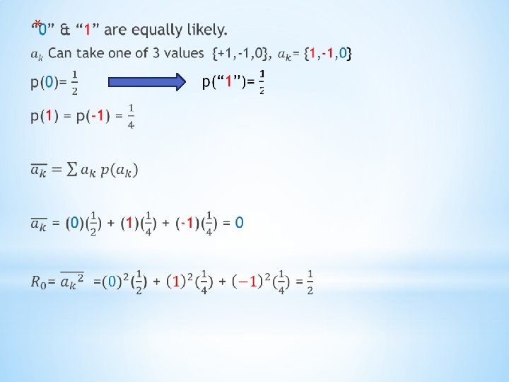
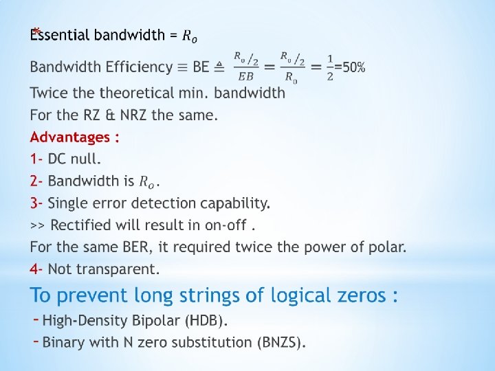
” 0” “ 1” No pulse Results in DC null in PSD. Use 0, 1, -1 ternary

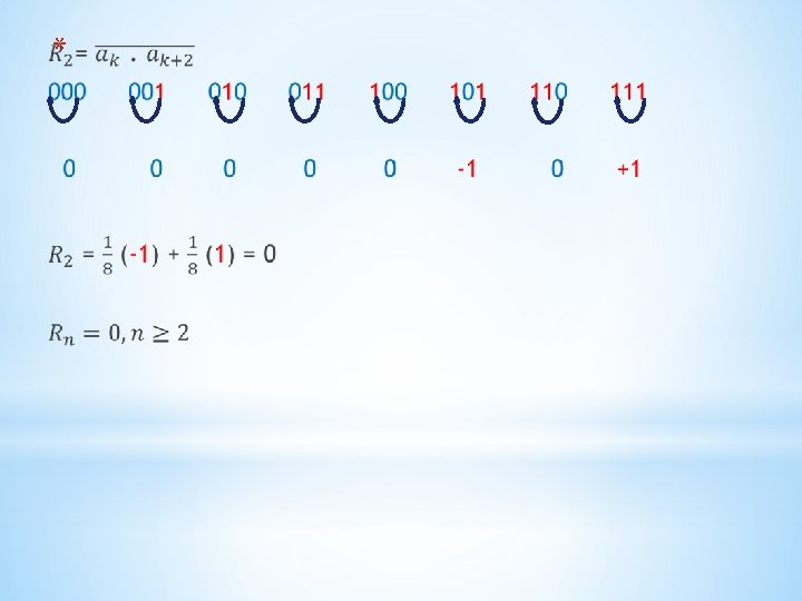
0 1 00 01 1 10 11 0 *

* 0 1 -1 0 0, 0 1, 0 -1, 0 1 0, 1 1, 1 -1 0, -1 1, -1 -1, -1 Impossible because of Bipolar rule

Don’t care 0 1 0 0 1 1 0 1 0 0 0 1 0 1 0 0 0 -1 0 1 -1 (1) 1 -1


EB

* * Bipolar rule Violates bipolar rule

* ⇛ DC=0 0 0 +1 0 -1 1 0 0 0 0 1 V 1 1 1 0 B 0 0 0 V

HDB 3 Bipolar EB

* * used in DS 1 000 VB ; DS 1 0 VB ; DS 2 ; DS 3
- Slides: 57