
Evaporationboiling Phenomena on Thin Capillary Wick Chen Li
Evaporation/boiling Phenomena on Thin Capillary Wick Chen Li G. P. Peterson Rensselaer Polytechnic Institute Department of Mechanical, Aerospace & Nuclear Engineering, Troy, NY 12180 Yaxiong Wang Foxconn Thermal Technology Inc. , Austin, TX 78758
How good is the performance of the evaporation/boiling on the thin capillary wick? q First 6 sets of data are from A. F. Mills Heat Transfer 1992 Richard D. Irwin, Inc. pp. 22. q Last set of data is from our experiments July 18, 2005 Two-Phase Heat Transfer Lab @ RPI
The porous media coating dramatically improves the Critical Heat Flux q All data are from our experiments July 18, 2005 Two-Phase Heat Transfer Lab @ RPI
Why use a THIN capillary wick? n Bubble departure diameter n Infinite fin length Dd(mm) Fritz’s model [1935] 2. 884 Cole and Rohsensow’s model [1969] 2. 426 July 18, 2005 Two-Phase Heat Transfer Lab @ RPI
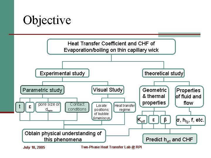
Objective Heat Transfer Coefficient and CHF of Evaporation/boiling on thin capillary wick Experimental study Visual Study Parametric study t ε pore size or dwire theoretical study Contact conditions Locate positions of bubble &meniscus Geometric & thermal properties Heat transfer regime Keff Obtain physical understanding of this phenomena July 18, 2005 Two-Phase Heat Transfer Lab @ RPI ε β Properties of fluid and flow σ, hfg, f, etc. Predict heff and CHF
What we could gain from perfect contact conditions? n reduce the heat flux density on the heated wall due to the fin effect; n contact points connecting the wick and wall could interrupt the formation of the vapor film and reduce the critical hydrodynamic wavelength; n significantly increase the nucleation site density and evaporation area; and n improve liquid supply through capillary force. July 18, 2005 Two-Phase Heat Transfer Lab @ RPI
Sintering process development n The use of a sintering process to fabricate the test articles was employed to reduce or eliminate the effect of thermal contact resistance between the porous wick material and the heating block July 18, 2005 Two-Phase Heat Transfer Lab @ RPI
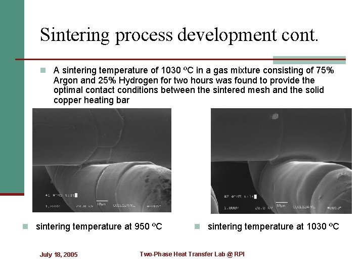
Sintering process development cont. n A sintering temperature of 1030 ºC in a gas mixture consisting of 75% Argon and 25% Hydrogen for two hours was found to provide the optimal contact conditions between the sintered mesh and the solid copper heating bar n sintering temperature at 950 ºC July 18, 2005 n sintering temperature at 1030 ºC Two-Phase Heat Transfer Lab @ RPI
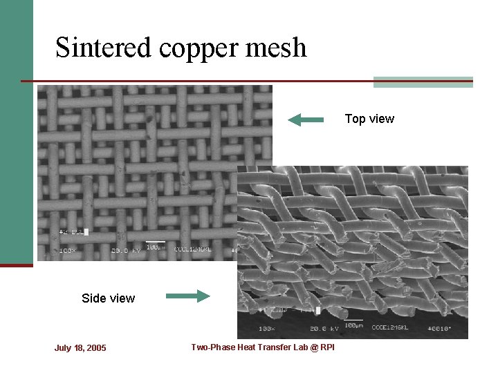
Sintered copper mesh Top view Side view July 18, 2005 Two-Phase Heat Transfer Lab @ RPI
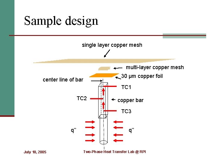
Sample design single layer copper mesh multi-layer copper mesh 30 µm copper foil center line of bar TC 1 TC 2 copper bar TC 3 q’’ July 18, 2005 q’’ Two-Phase Heat Transfer Lab @ RPI
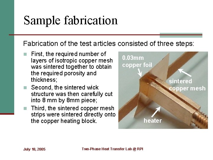
Sample fabrication Fabrication of the test articles consisted of three steps: n First, the required number of layers of isotropic copper mesh was sintered together to obtain the required porosity and thickness; n Second, the sintered wick structure was then carefully cut into 8 mm by 8 mm piece; n Third, the sintered copper mesh strips were sintered directly onto the copper heating block. July 18, 2005 0. 03 mm copper foil Two-Phase Heat Transfer Lab @ RPI sintered copper mesh heater
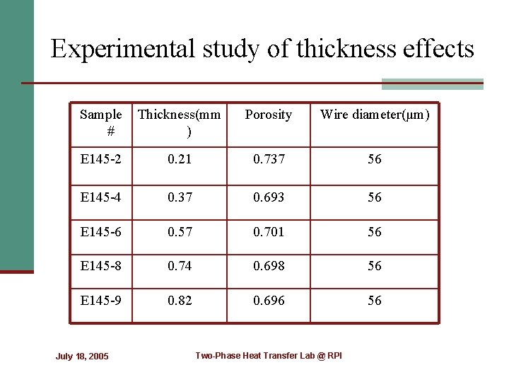
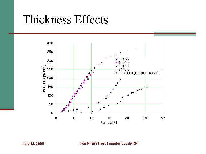
Experimental study of thickness effects Sample # Thickness(mm ) Porosity Wire diameter(μm) E 145 -2 0. 21 0. 737 56 E 145 -4 0. 37 0. 693 56 E 145 -6 0. 57 0. 701 56 E 145 -8 0. 74 0. 698 56 E 145 -9 0. 82 0. 696 56 July 18, 2005 Two-Phase Heat Transfer Lab @ RPI
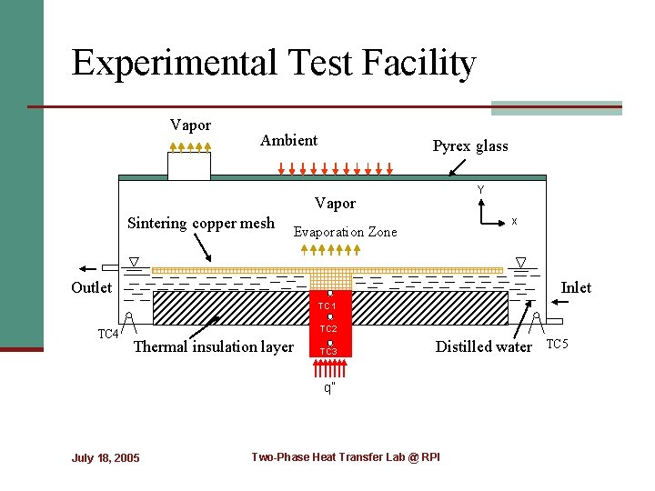
Experimental Test Facility Vapor Ambient Pyrex glass Y Vapor Sintering copper mesh x Evaporation Zone Outlet Inlet TC 1 TC 4 TC 2 Thermal insulation layer TC 3 Distilled water q” July 18, 2005 Two-Phase Heat Transfer Lab @ RPI TC 5
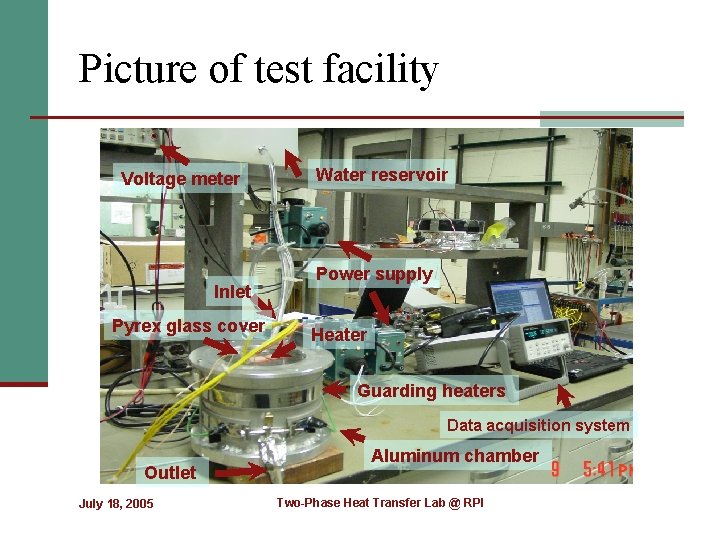
Picture of test facility Voltage meter Inlet Pyrex glass cover Water reservoir Power supply Heater Guarding heaters Data acquisition system Outlet July 18, 2005 Aluminum chamber Two-Phase Heat Transfer Lab @ RPI
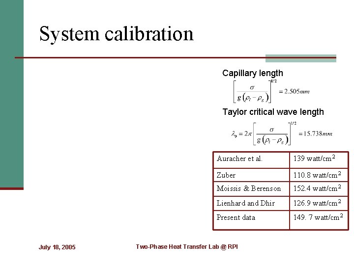
System calibration Capillary length Taylor critical wave length July 18, 2005 Auracher et al. 139 watt/cm 2 Zuber 110. 8 watt/cm 2 Moissis & Berenson 152. 4 watt/cm 2 Lienhard and Dhir 126. 9 watt/cm 2 Present data 149. 7 watt/cm 2 Two-Phase Heat Transfer Lab @ RPI
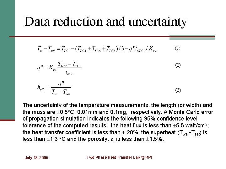
Data reduction and uncertainty (1) (2) (3) The uncertainty of the temperature measurements, the length (or width) and the mass are 0. 5 C, 0. 01 mm and 0. 1 mg, respectively. A Monte Carlo error of propagation simulation indicates the following 95% confidence level tolerance of the computed results: the heat flux is less than 5. 5 watt/cm 2; the heat transfer coefficient is less than 20%; the superheat (Twall-Tsat) is less than 1. 3 C and the porosity, ε, is less than 1. 5%. July 18, 2005 Two-Phase Heat Transfer Lab @ RPI
Contact conditions July 18, 2005 Two-Phase Heat Transfer Lab @ RPI
Contact conditions cont. July 18, 2005 Two-Phase Heat Transfer Lab @ RPI
Thickness Effects July 18, 2005 Two-Phase Heat Transfer Lab @ RPI
Thickness Effects cont. July 18, 2005 Two-Phase Heat Transfer Lab @ RPI
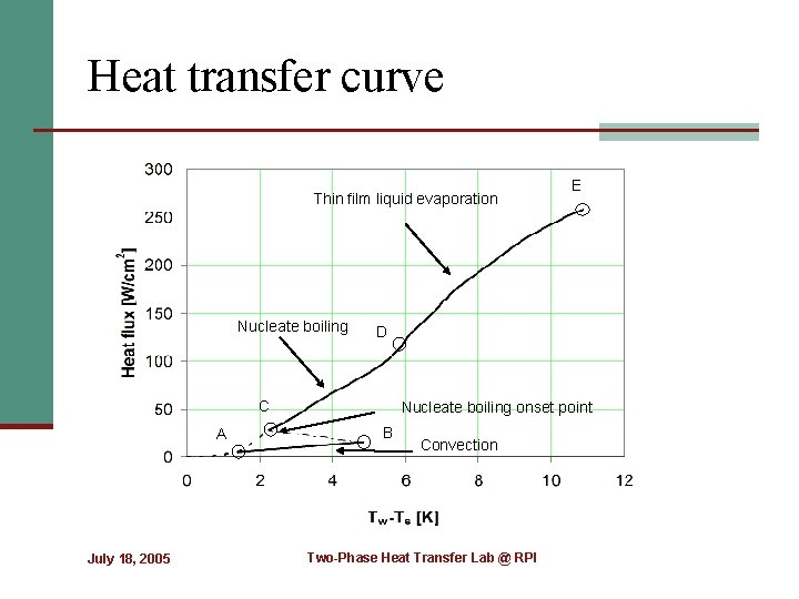
Heat transfer curve Thin film liquid evaporation Nucleate boiling D C A July 18, 2005 E Nucleate boiling onset point B Convection Two-Phase Heat Transfer Lab @ RPI
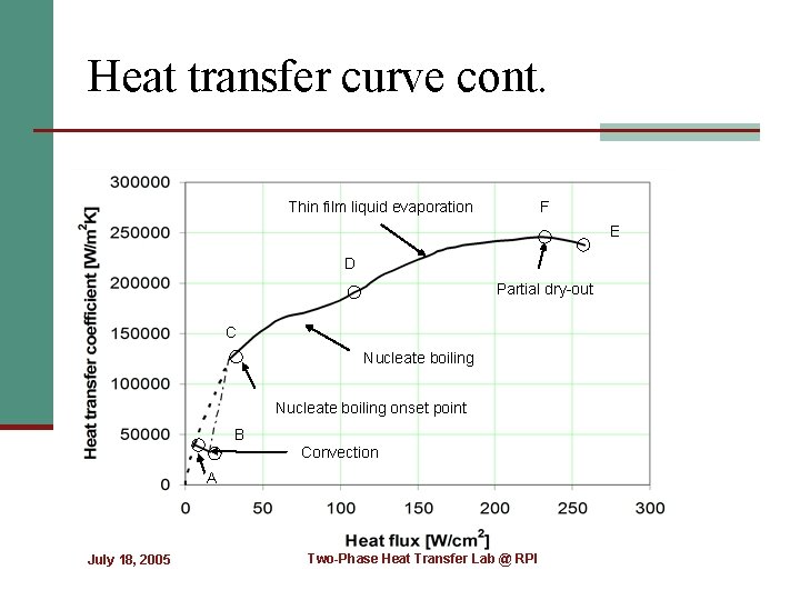
Heat transfer curve cont. Thin film liquid evaporation F E D Partial dry-out C Nucleate boiling onset point B Convection A July 18, 2005 Two-Phase Heat Transfer Lab @ RPI
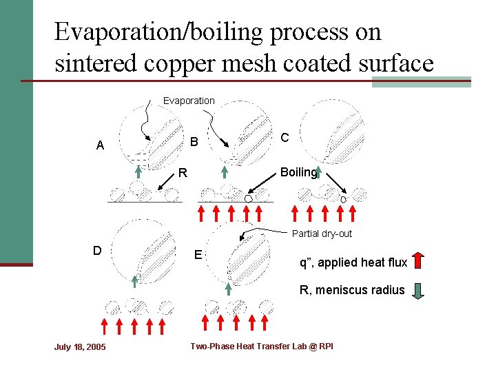
Evaporation/boiling process on sintered copper mesh coated surface Evaporation B A C Boiling R Partial dry-out D E q”, applied heat flux R, meniscus radius July 18, 2005 Two-Phase Heat Transfer Lab @ RPI
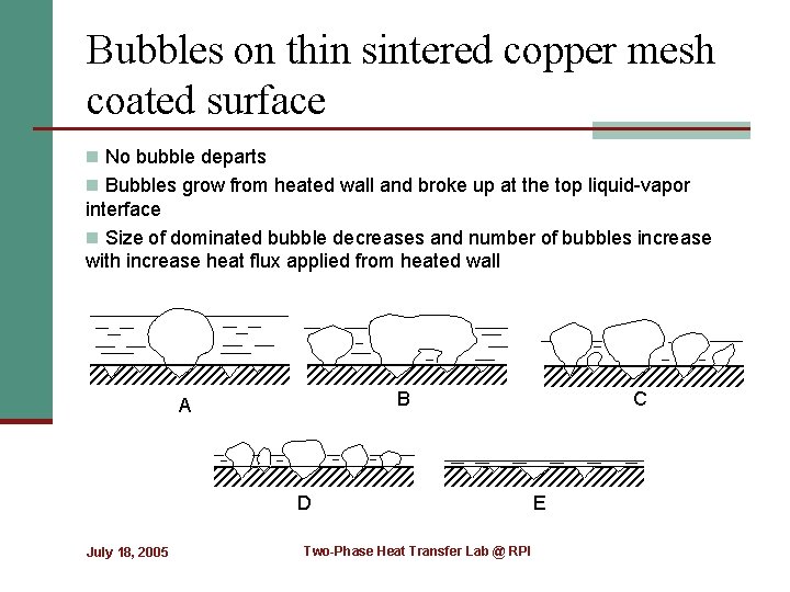
Bubbles on thin sintered copper mesh coated surface n No bubble departs n Bubbles grow from heated wall and broke up at the top liquid-vapor interface n Size of dominated bubble decreases and number of bubbles increase with increase heat flux applied from heated wall B A D July 18, 2005 Two-Phase Heat Transfer Lab @ RPI C E
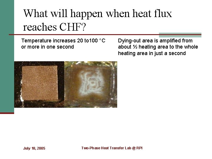
What will happen when heat flux reaches CHF? Temperature increases 20 to 100 °C or more in one second July 18, 2005 Dying-out area is amplified from about ½ heating area to the whole heating area in just a second Two-Phase Heat Transfer Lab @ RPI
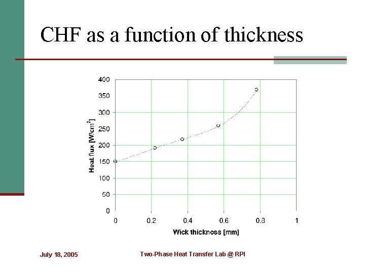
CHF as a function of thickness July 18, 2005 Two-Phase Heat Transfer Lab @ RPI
Main conclusions n The test results demonstrate that a porous surface comprised of sintered n n n isotropic copper mesh can dramatically enhance both the evaporation/boiling heat transfer coefficient and the CHF. The maximum heat transfer coefficients for the multiple layers of sintered copper mesh evaluated here were shown to be as high as 245. 4 KW/m 2 K and 360. 4 W/cm 2 respectively; The interface thermal contact resistance between the heated wall and the porous surface plays a critical role in the determination of the CHF and the evaporation/boiling heat transfer coefficient. Heat transfer regimes of evaporation/boiling phenomenon on this kind of wick structure have been proposed and discussed based on the visual observations of the phase-change phenomena and the heat flux-super heat relationship. For evaporation/boiling from the porous wick surface with a thickness ranging from 0. 37 mm to the bubble departure diameter, Db, the ideal heat transfer performance can be achieved and CHF is improved dramatically. The wick still works during partial dry-out and the capillary induced pumping functions effectively. Exposed area determines the heat transfer performance when other key parameters are held constant. July 18, 2005 Two-Phase Heat Transfer Lab @ RPI
Acknowledgments n The authors would like to acknowledge the support of the National Science Foundation under award CTS-0312848; July 18, 2005 Two-Phase Heat Transfer Lab @ RPI
n Thanks!! n Suggestions and Questions? July 18, 2005 Two-Phase Heat Transfer Lab @ RPI
- Slides: 29