European Summer School in Fuel Cells and Hydrogen


- Slides: 29

European Summer School in Fuel Cells and Hydrogen Technologies, Iraklion, Greece sunfire Gmb. H Synfuels from Electrolysis Dr. Oliver Posdziech, René Stäber, Christian von Olshausen 1

1. What is the motivation for synfuels? In the future fossil fuels will become short and the combustion creates climate-changing gases. Fuels from biomass compete with food production and can only be a partial solution. Furthermore there is a need for large scale storage for renewable energy (wind, solar) to synchronize supply and demand. sunfire is a 3 in 1 solution for some of the most significant challenges of our time Solar power Limited fossil resources Renewable fuel Photosynthesis Fluctuation in energy supply Energy storage / load balance Growing CO 2 -emission Biomass CO 2 + H 2 O CO 2 -recycling (alternative to CCS) Renewable fuels = Fossil resources like oil and gas 2

1. What is the motivation for synfuels? Despite of the expansion of the grid the necessity for storage increases due to renewable energy. Methane gas and liquid fuels are suitable to be used as efficient storages with large capacities. The fuel cell can be used to convert them efficiently back into electricity. Heat SOFC SOEC SOFC Electricity Mobility, Chemicals Storage, gas distribution system Oil/gas SOFC Pumped storage hydro power station, accumulator Electricity, E-mobility 3

2. The „C-H-O“-system Hydrogen is the starting point for the majority of substitutes for fossil based materials. Therefore SOECmodules must be developed with the aim that (1) efficient generation of hydrogen and (2) efficient conversion into carbon-containing materials are ensured. H 2 O (Water) Hydrogen Oxygen Hydrogen-Economy Efficient Generation Eff icie H 2 O + CO 2 (Combustion Products) nt ue ls (Gasoline, Diesel, Wax) n uc tio –G od 3 rd Fo ss il E ne rgy Fossil Ressources en . F CO 2 (Carbon Dioxide) Pr ion ers nv co CH 2 oedl. s y. PFru gn e r e G –n 3 sirld. E CH 2 O (Biomass) Fos C 6 H 2 O (Coal) Source: Dissertation Dr. B. M. Wolf, 1976 Carbon 4

3. The sunfire process – Overall overview The Sunfire process aims for maximum energetic efficiency. The flow diagram shows educts, products, basic 1 components and their combination: 5. H 2 O 2 -release 2 HH 2 O-steam 2 O-feed 3 HOT HXC 4 2 H 2 O-steam 4. CO 2 Syn. Gas 3. Energy input from electricity The steam electrolyser uses electric energy to produce hydrogen: H 2 O → H 2 + 0. 5 O 2 In the reverse water-gas shift reactor CO 2 and H 2 are mixed, heated and endothermic converted into syngas and water: CO 2 + 3 H 2 → CO + 2 H 2 + H 2 O The syngas is cooled by recuperation in counter-flow to the CO 2 and the steam from the FTcooling (see below). The cooled syngas flows into the CO -feed Fischer-Tropsch-reactor and turns into hydrocarbons and water. The surplus energy from this reactions is used to overcome the evaporation enthalpy of the H 2 O-feed: CO + 2 H 2 + H 2 O → - CH 2 - + 2 H 2 O Syn. Gas 1. 2. 1 -CH 2 fuel 5 H 2 O-feed MID fuel HXC COOL 5

3. The sunfire process - Introduction to enthalpy calculation The GIBBS-Energy G is named by the American physician Josiah Willard Gibbs. In chemistry it explains: If an reaction will happen, under which conditions it will happen and which volume of the involved substance will react. ΔG = ΔH – ΔT x S Simplified GIBBS equation ΔH = ΔG + ΔT x S Enthalpy = Electrical Energy + Thermal Energy ΔH > 0 : ΔH = 0 : ΔH > 0 : Exothermic reaction (provides energy) Balance reaction (no reaction) Endothermic reaction (energy is required) ΔG < 0 : ΔG = 0 : ΔG > 0 : Voluntary reaction Equilibrium reaction (no reaction) Involuntary reaction (needs energy) 6

3. The sunfire process - Introduction to enthalpy calculation The GIBBS-Energy G is named by the American physician Josiah Willard Gibbs. In chemistry it explains: If an reaction will happen, under which conditions it will happen and which volume of the involved substance will react. Example for enthalpy calculation from enthalpy of formation: RWGS reaction CO 2 + 3 H 2 → CO + 2 H 2 + H 2 Og ΔHf [k. J/mol] -394 + 3 x 0 → -111 + 2 x 0 + -242 -394 ΔHr = ∑ ΔHf. Products - ∑ ΔHf, Educts -353 = -353 k. J/mol = +41 k. J/mol - (-394 k. J/mol) 7

3. The sunfire process – Electrolysis The Solid Oxide Electrolyze Cell-technology for conversion of H 2 O and CO 2 firstly was demonstrated in the 1960 s by the NASA. Nowadays, SOEC development is in process and uses gained knowledge from the SOFC-technology, that is very similar to it. Requirements for steam electrolysis in the sunfire process: H 2 O-steam O 2 -release • Stable production of H 2 • H 2 O conversion rate > 50%, preferably > 70% • CO 2 – electrolysis is advantageous but not necessarily required • No internal heating required, endothermic mode is preferred • Steam of constant temperature (up to 900°C; dep. on requirement) and constant pressure is supplied by the sunfire-process. • For the application on industrial scale pressurized operation is required (up to 30 bars) saves energy to compress the gases 8

3. The sunfire process – Conversion In the reverse water-gas shift reactor CO 2 and H 2 react endothermically into CO + H 2 O. It is the first of two CO 2 -reduction steps. The reverse water-gas shift reactor consists of an electric heater and a reaction zone. The reaction firstly was discovered by Italian physicist Felice Fontana in 1780. Requirements for reverse water-gas shift reactor (RWGS): CO 2 H 2 Syn. Gas • Heater levels the temperature of the CO 2 + H 2 – mixture in order to achieve the achieved equilibrium. • Required temperature is between 800°C – 1500°C. • The reactor contains a fixed bed catalytic reaction zone and works under pressures of 20 – 30 bars. • The reverse water-gas shift reactor could be replaced by CO 2/H 2 O – coelectrolysis • However, it allows the exact leveling of thermodynamic equilibrium and can also decompose stable (but unwanted) byproducts from the Fischer-Tropsch-synthesis. 9

3. The sunfire process – Syntheses The Fischer-Tropsch technology has been applied for many decades. Since the invention of the original process by Franz Fischer and Hans Tropsch, working at the Kaiser-Wilhelm-Institut for Chemistry in the 1920 s, many refinements and adjustments have been made. Requirements for Fischer-Tropsch reactor Syn. Gas H 2 O-steam • Sunfire aims for an operation at 20 -30 bars using a cobalt catalyst • Sunfire can build up on the know-how of CHOREN, including a specific patent. 2 H 2 + H 2 O + CO → CH 2 + 2 H 2 O-feed fuel - 147 k. J/mol Requirements for Methanation reactor (Sabatier) • Operation pressure is also 20 -30 bar • A nickel catalyst is used 4 H 2 + CO 2 → CH 4 + 2 H 2 O - 164 k. J/mol 10

4. Comparison water electrolyze vs. sunfire process Water electrolysis uses electrical energy for (1) passing the level from liquid to gaseous phase of water and (2) cracking it into hydrogen and oxygen. The maximum efficiency of this process is limited to 84% because of the difference between higher and lower heating value. 3 H 2 Usage -726 k. J/mol Electrolysis +726 k. J/mol Insert energy 1, 19 k. Jel/k. JH 2 3 H 2 O steam Condensation -141 k. J/mol Evaporation +141 k. J/mol 3 H 2 O liquid ηmax theor. = 726/(141 + 726) = 84% = 620/(141 + 726+41) = 68% (incl. RWGS+FT-synthesis) 11

4. Comparison water electrolyze vs. sunfire process Sunfire produces H 2 endothermically and increases the heating value by mixing it with CO 2 to syngas. Afterwards the syngas gets converted in a endothermic reaction to fuel and water. The exothermal energy of the synthesis is used to evaporate the needed water. Conversion + 41 k. J CO 2 Syngas CO + H 2 O + 2 H 2 CH 2 + 2 H 2 O CO 2 + 3 H 2 Steam electrolyze +726 k. J Syntheses -146 k. J Usage -620 k. J Recuperation 3 H 2 Osteam CO 2 + 3 H 2 O Evaporation +141 k. J Condensation -141 k. J/mol 3 H 2 O liquid ηmax theor. = 620/(726 + 41) = 81% (incl. RWGS+FT-synthesis) 12

5. Process paths of the sunfire process For infrastructure-compatible fuels (-CH 2 -, CH 4) there are five main paths that shall be analyzed regarding their maximum efficiency. A: Liquids via H 2 O-SOEC + RWGS + Fischer-Tropsch Maximum efficiency: +141 k. J/mol +726 k. J/mol + 41 k. J/mol Recuperation a) Evaporation: 3 H 2 OL → 3 H 2 OG b) H 2 O – Electrolysis: 3 H 2 OG → 3 H 2 + 1, 5 O 2 c) RWGS: 3 H 2 + CO 2 → 2 H 2 + CO + H 2 O d) FT – synthesis: 2 H 2 + H 2 O + CO → CH 2 + 2 H 2 O - 147 k. J/mol η = LHVfuel/Ein electric 620 k. J/mol / (+141+726+41 -147+6) k. J/mol = 81% Non-recuperable excess heat from synthesis: 6 k. J/mol 13

5. Process paths of the sunfire process For infrastructure-compatible fuels (-CH 2 -, CH 4) there are five main paths that shall be analyzed regarding their maximum efficiency. a) Evaporation: 2 H 2 OL → 2 H 2 OG + 94 k. J/mol b) H 2 O/CO 2 – Electrolysis: 2 H 2 OG+CO 2 → 2 H 2+CO+1, 5 O 2 +767 k. J/mol c) FT – synthesis: 2 H 2 + CO → CH 2 + H 2 O - 147 k. J/mol Maximum efficiency: Recuperation B: Liquids via H 2 O/CO 2 -SOEC + Fischer-Tropsch η = LHVfuel/Ein electric 620 k. J/mol / (+94+767 -147+53) k. J/mol = 81% Non-recuperable excess heat from synthesis: 53 k. J/mol 14

5. Process paths of the sunfire process For infrastructure-compatible fuels (-CH 2 -, CH 4) there are five main paths that shall be analyzed regarding their maximum efficiency. C: Methane via H 2 O-SOEC + RWGS + Methanation Maximum efficiency: +188 k. J/mol +968 k. J/mol + 41 k. J/mol Recuperation a) Evaporation: 4 H 2 OL → 4 H 2 OG b) H 2 O – Electrolysis: 4 H 2 OG → 4 H 2 + 2 O 2 c) RWGS: 4 H 2 + CO 2 → 3 H 2 + CO + H 2 O d) CH 4 – synthesis: 3 H 2 + H 2 O + CO → CH 4 + 2 H 2 O - 205 k. J/mol η = LHVfuel/Ein electric 804 k. J/mol / (+188+968+41 -205+17) k. J/mol = 80% Non-recuperable excess heat from synthesis: 17 k. J/mol 15

5. Process paths of the sunfire process For infrastructure-compatible fuels (-CH 2 -, CH 4) there are five main paths that shall be analyzed regarding their maximum efficiency. D: Methane via H 2 O/CO 2 -SOEC + Methanation Recuperation a) Evaporation: 3 H 2 OL → 3 H 2 OG +141 k. J/mol b) H 2 O/CO 2 – Electrolysis: 3 H 2 OG + CO 2 → 3 H 2 + CO + 2 O 2 +1009 k. J/mol c) CH 4 – synthesis: 3 H 2 + CO → CH 4 + H 2 O - 205 k. J/mol Maximum efficiency: η = LHVfuel/Ein electric 804 k. J/mol / (141+1009 -205+64) k. J/mol = 80% Non-recuperable excess heat from synthesis: 64 k. J/mol 16

5. Process paths of the sunfire process For infrastructure-compatible fuels (-CH 2 -, CH 4) there are five main paths that shall be analyzed regarding their maximum efficiency. E: Methane via H 2 O-SOEC + Sabatier-Methanation Maximum efficiency: +188 k. J/mol +968 k. J/mol - 164 k. J/mol Recuperation a) Evaporation: 4 H 2 OL → 4 H 2 OG b) H 2 O – Electrolysis: 4 H 2 OG → 4 H 2 + 2 O 2 c) Sabatier: 4 H 2 + CO 2 → CH 4 + 2 H 2 O η = LHVfuel/Ein electric 804 k. J/mol / (+188+968 -164) k. J/mol = 81% Non-recuperable excess heat from synthesis: 0 k. J/mol 17

5. Process paths of the sunfire process Conclusion: 1. For Liquids, A & B shall show similar process efficiencies but B may have less Capex (Capital Expenditures) (no RWGS component). 2. Efficiency of B can only be increased if additional redundant excess heat can be recuperated back into the process (nuclear power station). 3. For Methanation, RWGS or H 2 O/CO 2 -Coeelectrolysis reduces overall efficiency as it increases electric energy demand. 18

6. Systemic requirements – Area Specific Resistance (ASR) As overall system efficiency cannot increase beyond the maximum power level, the TN is the point of optimum operation to leverage the capacity of the cell area. Running exothermically significantly lowers the system efficiency. SOEC-efficiency has the highest effect on overall system efficiency. Overall process efficiency (LHVfuel/Eel) Electrolysis Efficiency (LHVH 2/CO/Eel) 19 Source: sunfire Gmb. H, 2012

6. Systemic requirements – SOEC pressure level The pressure level of the SOEC has the second highest impact on overall system efficiency. This is due to the low efficiency of gas compression compared to the high efficiency of a water pump. Overall process efficiency (LHVfuel/Eel) H 2 compression work Electrolysis pressure level 20 Source: sunfire Gmb. H, 2012

7. Downstream process steps for liquid fuels H 2 The FT – syntheses creates fractions of naphtha (C 5 – C 10), diesel (C 11 – C 20) and wax (>C 20). These fractions merely consist of unbranched alkanes. Because of the resulting properties the fractions need to be treated afterwards before they can be used. ax ) a, ht h a, na ns ( ct io io ra ct 2 -f ra H 2 -f -C H x) wa -C s( on FT-synthesis th ph ns ti ac H 2 O-feed di es di el) es el , w H 2 O-steam (n -fr H 2 ap -C Syn. Gas Synfuel Hydrocracking Distillation / Reforming 21

7. Downstream process steps for liquid fuels The FT – syntheses creates fractions of naphtha (C 5 – C 10), diesel (C 11 – C 20) and wax (>C 20). These fractions merely consist of unbranched alkanes. Because of the resulting properties the fractions need to be treated afterwards before they can be used. Reforming • the difference between naphtha and petrol (gasoline) is the octane index • for a common usability the octane index of naphtha (n=20 -30) needs to be increased (n>90) • the distillation is necessary to split naphtha into light petrol (n=5, 6) and heavy petrol (n=7 -10) • light petrol flows into an isomerisation process where isoalkanes are created • heavy petrol flows into a reforming process where they react to aromatics • all reforming processes are standard refinery processes. 22

7. Downstream process steps for liquid fuels The FT – syntheses creates fractions of naphtha (C 5 – C 10), diesel (C 11 – C 20) and wax (>C 20). These fractions consists of unbranched alkanes to a high amount. Because of the resulting properties the fractions need to be treated afterwards before they can be used. Hydrocracking • long chains of wax will be cracked into shorter chains like petrol and diesel • hydrocracking uses pressure and hydrogenic atmosphere for: • cracking long chains into shorter fractions • removing S and N by converting them into H 2 S and NH 3 23

8. CO 2 – sources The major educts for the whole process are H 2 O and CO 2. While H 2 O supply is easily available in most cases, CO 2 -sources need to be identified. Example sources for CO 2 supply [t/a] Resulting fuel capacity for the sunfire process [t/d] burning of biomass (e. g. 20 MWel produces 213, 000 t/a CO 2) 180 t/d gasification of biomass (e. g. 500 k. Wel produces 12 t/d CO 2) 2 t/d production of bioethanol (e. g. 205, 000 t ethanol/a produces 265, 000 t/a CO 2) 220 t/d burning of brown coal (e. g. 500 MWel produces 4, 400, 000 t/a CO 2) 3, 750 t/d producing of cement (e. g. produces in average 800, 000 t/a CO 2) 684 t/d → in future it is also possible to capture CO 2 from air Production in refinery: 34, 000 t/d 24

9. Economic efficiency In the future sunfire will be the supplier for the core technology and also supplier for engineering of equipment to produce fuels. The requirement for the success of sunfire are competitive prime costs. The willingness to pay for renewable fuels is above 1€/l. Comparison of costs (€/l) Ø prime costs (€/l) Fossil diesel price 2. 50€/l 2. 00€/l sunfire-costs Costs per liter (incl. tax ) sunfire-price incl. economic differential + 50% abatement of tax Energy costs 0, 69 €/l Capex 0, 10 €/l Opex 0, 08 €/l Transportation and distribution 0, 08 €/l Total 0, 95 €/l sunfire-price incl. economic differential 1. 50€/l 1. 00€/l 0. 50€/l 0. 00€/l 100. 00 $/bbl 120. 00 $/bbl 140. 00 $/bbl 160. 00 $/bbl 180. 00 $/bbl 200. 00 $/bbl 25

9. Economic efficiency Worldwide the market of renewable fuels is controlled by political guidelines. In Europe the sustainability order (2009/28/EG) from 2017 implies that a lot of 1 st generation biofuels are not allowed anymore. At the same time the statutory blending rate for biofuels as part of fossil fuels increases to 10%. In 2020 the need for renewable fuels at the EU will be 37, 4 mto/a 37. 4 40. 0 35. 0 30. 0 Angebot Supply Demand Nachfrage Demand increases: In 2020 the part of energy based on renewable sources needs to be 10% (today 6, 5%) of the consumption of end-use energy at all common carriers. Demand +143% 25. 0 20. 0 Supply decreases: In 2017 the abatement of greenhouse gas emissions by using biofuels needs to be at least 50% (new plants 60% as of 2018) 15. 4 15. 0 5. 2 10. 0 Demand Supply -66% 5. 0 Supply In mto 0. 0 2010 2020 Nachfrage Angebot 26

10. Development Outlook The first SOEC prototype will be developed by sunfire together with a group of partners. SOEC – development goals for first prototype • • • Size ASR Degradation: Pressure Steam Utlisation Power Modulation • Commercial goal: Available as single unit and/or integrated into fuel producing system. ca. 10 k. W < 0, 4 Ω*cm² < 3%/1000 hrs up to 30 bar > 70% 20% – 100% within 15 minutes 27

Summary • Production of synfuels from renewable electricity is one viable option to deal with fluctuating sources • SOEC technology is the method of choice to reach high conversion efficiencies from H 2 O/electricity to synfuels like methane or liquid fuels (diesel / gasoline / kerosene) • For methanation, a separate RWGS-unit or co-electrolysis to form CO before entering CH 4 -synthesis lower overall process efficiency compared to pure H 2 O-electrolysis and subsequent methanation directly starting from CO 2 • An advantage in energetic efficiency via co-electrolysis can only be realized if the resulting additional excess heat from the subsequent synthesis can be utilized. • The overall efficiency for processes forming fuels out of CO 2 and H 2 O utilizing SOEC mainly depends on the efficiency of the SOEC with a sensivity factor of ca. 0. 8. • The pressure level of the SOEC also has a significant impact on overall process efficiency. If hydrogen or syngas have to be compressed from 1 bar to 30 bars the overall process efficiency is lowered by more than 5%. • RWGS efficiency has a lower sensitivity factor of 0. 03 as the overall energy feed in share from RWGS is rather low. 28

Sun. Fire Gmb. H Gasanstaltraße 2 01237 Dresden Deutschland www. sunfire. de kontakt@sunfire. de Tel: +49 (0) 351 89 67 97 908 Fax: +49 (0) 351 89 67 97 868
 Valuetheenergy.com
 Paranasal sinuses development
 Chlorocruorin
 Animal cell venn diagram
 Masses of cells form and steal nutrients from healthy cells
 Tubular lumen
 Parafollicular
 Somatic cells vs gametes
 Why dna is more stable than rna?
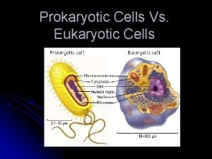
 Prokaryotes vs eukaryotes
 Prokaryotic cells vs eukaryotic cells
 The organelle trail
 Label
Label 4 types of eukaryotic cells
 Prokaryotic cell wall
 Nondisjunction in meiosis
 Cell substance
 Lodi summer school
 Crescenta valley high school graduation 2021
 Assignment in spanish
 Eeb3 apeee
 Tallinn
 European school of antennas
 European school net academy
 Hydrogen energy advantages and disadvantages
 Experimental study of hydrogen release and ignition from
 Salt and hydrogen
 Covalent bond for hydrogen and chlorine
 Reaction between copper oxide and hydrogen
 Hydrochloric acid and sodium hydrogen carbonate reaction
