Ethernet Frame Preamble Destination Address Source Address Length

Ethernet Frame Preamble Destination Address Source Address Length/ Type LLC/ Data Frame Check Sequence

Ethernet Addresses 48 bit n normally shown in HEX n e. g. : 02 -60 -8 C-44 -59 -E 0 n first 24 bits are obtained from IEEE by hardware manufacturers n one bit is used to distinguish unicast from multicast addresses n one bit is used to distinguish locally assigned addresses(rare) from globally assigned addresses (typical) n

Transmission Types Unicast - intended for one specific station n Broadcast - intended for all stations n Multicast - intended for a group of stations n

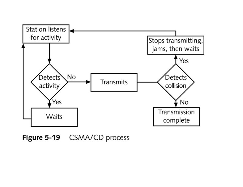
CSMA/CD Carrier Sense, Multiple Access with Collision Detection n Carrier sense - don't transmit if there is already a signal n Collision detection - if a collision is detected jam, wait, and retransmit n

No Carrier

Transmission

Transmission

End of Transmission

Transmission

Second Transmission

Collision

Collision detected

Wait
 • • Layer 1 device Repeat signal on all ports Enforce")
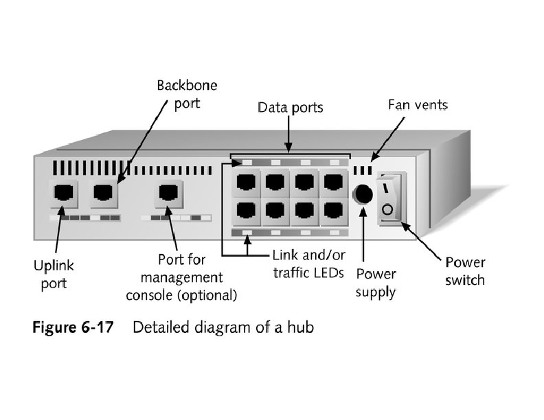
Ethernet HUB (repeater) • • Layer 1 device Repeat signal on all ports Enforce collision on all segments (jam) Restore amplitude of the signal Retime the signal Single speed May mix media

Repeater Hub

Repeater Hub one station transmits

Repeater Hub signal repeated on all other ports

Repeater Hub signal repeated on all other ports

Repeater Hub end of transmission

Repeater Hub

Matrix Module

Collision Domain • Devices connected by hubs • Only one device can transmit at a time • Collisions detected by all devices in the domain

One Collision Domain Hub Hub

Broadcast Domain • • Devices connected by switches Can contain multiple collision domains One transmission in each collision domain Collisions do not propagate between collision domains • Broadcast frames do propagate to all collision domains • Can be full duplex if only two devices in collision domain and both devices are full duplex cabable

Three Collision Domains One Broadcast Domain Switch Hub

H – Ethernet Hub S – Ethernet Switch R – IP Router R W – Workstation _____ Ethernet Segment S S H W W S H H H W W W W

H – Ethernet Hub S – Ethernet Switch R – IP Router R W – Workstation _____ Ethernet Segment S S H W W S H H H W W W W

H – Ethernet Hub S – Ethernet Switch R – IP Router R W – Workstation _____ Ethernet Segment S S H W W S H H H W W W W

H – Ethernet Hub S – Ethernet Switch R – IP Router R W – Workstation _____ Ethernet Segment S S H W W S H H H W W W W
 “bridge” Forwards or Filters unicasts Floods")
Ethernet switch • • • Function (old name) “bridge” Forwards or Filters unicasts Floods (forwards to all ports) all broadcasts Learns address locations Can be full duplex if only two devices in collision domain and both devices are full duplex cabable • Can mix speeds and media
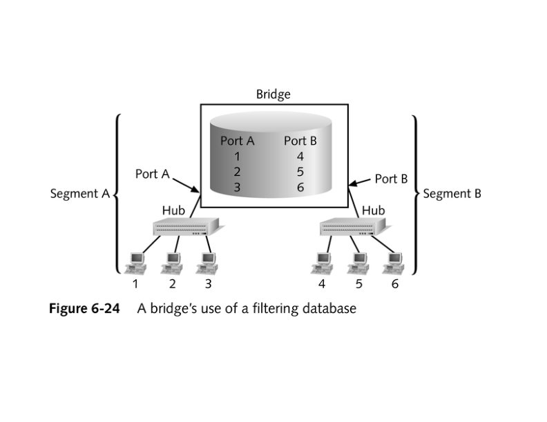

switch 1 D A SA Action FF E 2 E 3 E 2 FF E 5 E 6 E 5 E 4 E 1 Hub Hub E 1 3 2 E 3 E 5 E 4 ADDRE SS PORT E 6
 • Switch Lights – more(5. 9")
Switch Light Videos • Switch Lights(3. 5 MB) • Switch Lights – more(5. 9 MB)

Cut-Through Mode and Store and Forward Mode • Cut-through mode – Switching mode in which switch reads a frame’s header and decides where to forward the data before it receives the entire packet – Can detect runts, or packet fragments • Store and forward mode – Switching mode in which switch reads the entire data frame into its memory and checks it for accuracy before transmitting it
 – Means by")
Using Switches to Create VLANs • Virtual local area networks (VLANs) – Means by which a switch can logically group a number of ports into a broadcast domain • Broadcast domain – Combination of ports that make up a Layer 2 segment and must be connected to a Layer 3 device FIGURE 6 -24 Simple VLAN design

Trunk Aggregation

Resilient Links

Higher-Layer Switches • Switch capable of interpreting Layer 3 is called a Layer 3 switch • Switch capable of interpreting Layer 4 is called a Layer 4 switch • Higher-layer switches may also be called routing switches or application switches

Routers • Multiport device • Can connect dissimilar LANs and WANs running at different transmission speeds and using a variety of protocols

Router Features and Functions • Filter out broadcast transmission to alleviate network • • • congestion Prevent certain types of traffic from getting to a network Support simultaneous local and remote activity Provide high network fault tolerance through redundant components Monitor network traffic and report statistics to a MIB Diagnose internal or other connectivity problems and trigger alarms

Routers FIGURE 6 -26 Placement of routers on a LAN

Routing Protocols • Means by which routers communicate with each other about network status – Convergence time • The time it takes for a router to recognize a best path in the event of a change or outage – Bandwidth overhead • Burden placed on an underlying network to support the routing protocol
 for IP and IPX • OSPF (Open")
Routing Protocols • RIP (Routing Information Protocol) for IP and IPX • OSPF (Open Shortest Path First) for IP – Best path refers to the most efficient route from one node on a network to another • EIGRP (Enhanced Interior Gateway Routing Protocol) for IP, IPX, and Apple. Talk • BGP (Border Gateway Protocol) for IP

Gateways • Combination of networking hardware and software that connects two dissimilar kinds of networks – – E-mail gateway IBM host gateway Internet gateway LAN gateway
- Slides: 52