ESS Tuning Dump Vessel Actuator Design CDR Danish

 Mark Ibison (University of Liverpool) Erik")


: • All ports are DN 250 size dia. 860. 6 mm")


 600 mm Limit switches")


- Slides: 29
ESS Tuning Dump Vessel Actuator Design CDR Danish Naeem 07 th Nov 2018
Attendees: • • Danish Naeem (STFC Daresbury Lab) Mark Ibison (University of Liverpool) Erik Adli (Oslo) Greyson Christoforo (Oslo) Håvard Gjersdal (Oslo, Optional) Cyrille Thomas (ESS, Optional) Thomas Shea (ESS, Optional) Fabio Ravelli (ESS, Optional)
Scope: • • Procurement of Actuators with motors Design and Procurement of mating flanges for vessel Design and Procurement of mating flanges for Actuators Procurement of Limit Switches Procurement of view ports Assembly and testing of above Packing and Delivery to Oslo / ESS Sweden • Design and Procurement of vessel for Tuning Dump is covered by ESS BTM WP 12.
Quantities to Deliver:
CDR Objective: • To get approval for vessel manufacture. • To get approval for procurement of Actuator and view port. • To get approval for rest of the items.
Vessel Design
Original Design: • Only 1 vessel • Location: At the end of dump line before Gamma blocker Vacuum Vessel
Final Design: • • • Length significantly reduced Angular ports removed Rotatable flanges except Bottom flange. • • • Location changed Qty increased Top & View port flange is 2 piece rotatable.
Dimensions (New Design): • All ports are DN 250 size dia. 860. 6 mm 1102. 3 mm Top View 45º
Location of New vessel: The vessel quantity in dump line has been increased from 1 to 3. Where 2 vessels closure to the dump will be fully equipped with screen imaging system while 3 rd vessel will work as beam pipe and future upgrade for ESS. The location for 2 new vessel has been chosen as to replace the 4 -way tee crosses which exist earlier in the dump line. This will be done at 2 different locations in the dump line as shown below. This decision has been made by Oslo and Uni. Of Liverpool jointly but requires ESS approval. 3157. 5 mm 1240 mm 1 2 4 way Tee crosses 3
After replacement of Tee crosses with new vessel Vacuum Vessel Beam End 5497. 5 m m Dump End The length of new vessel is same as the length of Tee crosses replaced here. The vertical height of new vessel is determined based on travel and size required for screens.
Actuator Design
Actuator design is provided by UHV motion. Travel is 600 mm based on screen travel required. Phytron Stepper motor with limit and home switch included. Mounted on top of the vessel via transition flange. Size DN 63 860 mm • • • Bolted as shown Top and bottom
Vessel Mounting Flanges
• • • The vessel vertical port will be equipped with 2 flanges. Both flanges will be DN 250 CF bolted with knife edge. The bottom flange will be a standard CF bolted blank flange. The top flange will be a standard CF bolted flange with modification i. e. a bore in centre to suit central rod passing through and a bolt pattern holes to suit DN 63 flange bolt holes. Top flange will have knife edge on both faces to provide vacuum seal. Top flange will have blind threaded holes to provide lifting aid. Both flanges will mate with vessel welded rotatable flanges using bolts. Bottom Blank Flange Top Bored Flange With bolt holes Top Flange connection with vessel and DN 63 Flange
Actuator Mounting Flanges
• • • The actuator will be equipped with 2 flanges at top and bottom. Both flanges will be DN 63 CF with knife edge. The bottom flange will sandwiched between actuator and vessel DN 250 CF flange. Bottom Flange will have knife edge on both faces to provide vacuum seal. The top flange will be a standard CF blank flange with modification i. e. a blind tapped hole in centre to suit central rod and a bolt pattern holes to suit DN 63 flange bolt holes. Both flanges will be held in place using cap head screws. Bottom Flange Top Bored Flange With bolt holes
Top Flange connection with Actuator Bottom Flange connection with vessel Flange and Actuator
Limit Switches Design
Limit Switches : • • All limit switches will be procured from Crouzet 83160 family. Full designation is SF 133210_B 83160154. All limit switches are roller type with special contacts. Actuator supplier need to be informed on limit switch positions as the actuator support needs to be modified to allow installation of these switches onto actuator.
• Location of Limit Switches (TBC) 600 mm Limit switches
Testing
1. A detailed test procedure document will be written by STFC at the time due for testing. 2. Major tests are as follows I. Visual and dimensional inspection of all incoming items i. e. purchased items II. All items will go through vacuum cleaning process III. Independent Actuator test before assembling onto the vessel to ensure its working. Oslo to conduct this. IV. Electronics, motion controller, wiring tests to be conducted by Oslo. V. Vacuum vessel cleaning, RGA scan, pumping and any other vacuum tests to be conducted by STFC. All these tests for vacuum vessel are covered in ESS BTM WP 12. VI. After assembly tests of actuator, screen positioning, location and working of limit switches to be done by both STFC and Oslo.
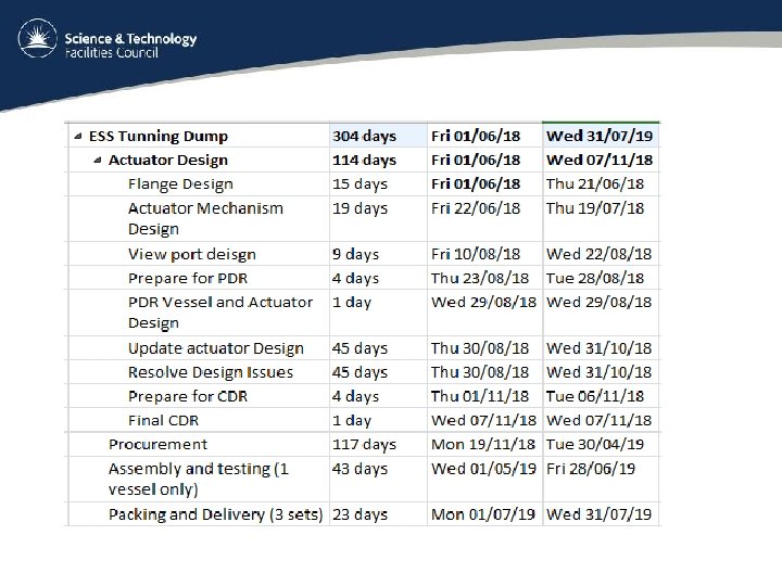
Schedule
Costs
1. A formal quotation has been issued to Oslo for the STFC works on this work package. 2. Quotation is under review with Oslo and will be signed shortly. 3. STFC will not proceed with any order until formal quotation has been signed and agreed. 4. All prices in quotation are based on current valid quotation from different supplier but final prices will be determined at the time of placement of order. 5. Quotation price of actuator has already gone up from supplier due to phytron motors and crouzet limit switches. 6. Any changes in prices will be reflected in final invoice to Oslo unless those changes are already covered.
Approvals
1. Do STFC have approval for vessel manufacture? 2. Do STFC have approval for Actuator order placement? 3. Do STFC have approval for View port order placement? Please note that despite the client approvals, STFC will still have to go through internal approval process and acquiring 3 quotations for each item purchased.