
ESS Medium Beta Cavities Rocco Paparella on behalf

ESS Medium Beta Cavities Rocco Paparella on behalf of INFN Milano – LASA ESS Team www. europeanspallationsource. se SLHi. PP-6 - STFC - May 24 th, 2016
Talk: Overview • Medium Beta section – Requirements – INFN IK contribution • Prototypes – EM design – Mechanical design – Infrastructure • Series – Procurements – QA/QC – Planning • Summary SLHi. PP-6 - STFC - May 24 th 2016 2
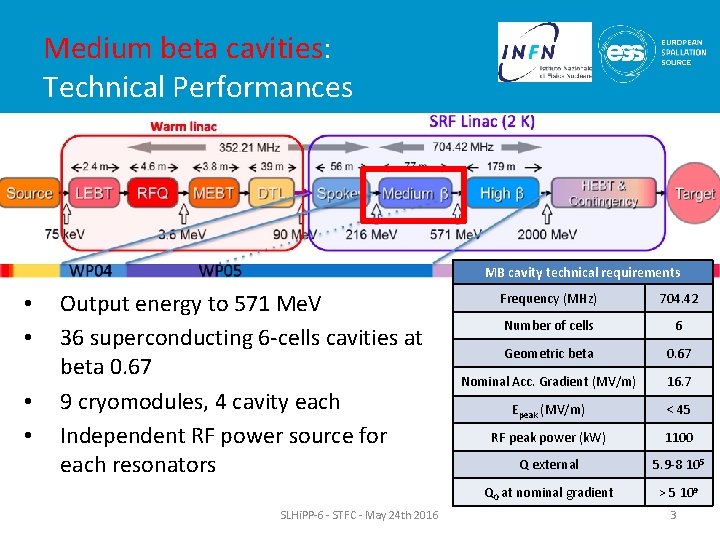
Medium beta cavities: Technical Performances MB cavity technical requirements • • Output energy to 571 Me. V 36 superconducting 6 -cells cavities at beta 0. 67 9 cryomodules, 4 cavity each Independent RF power source for each resonators SLHi. PP-6 - STFC - May 24 th 2016 Frequency (MHz) 704. 42 Number of cells 6 Geometric beta 0. 67 Nominal Acc. Gradient (MV/m) 16. 7 Epeak (MV/m) < 45 RF peak power (k. W) 1100 Q external 5. 9 -8 105 Q 0 at nominal gradient > 5 109 3
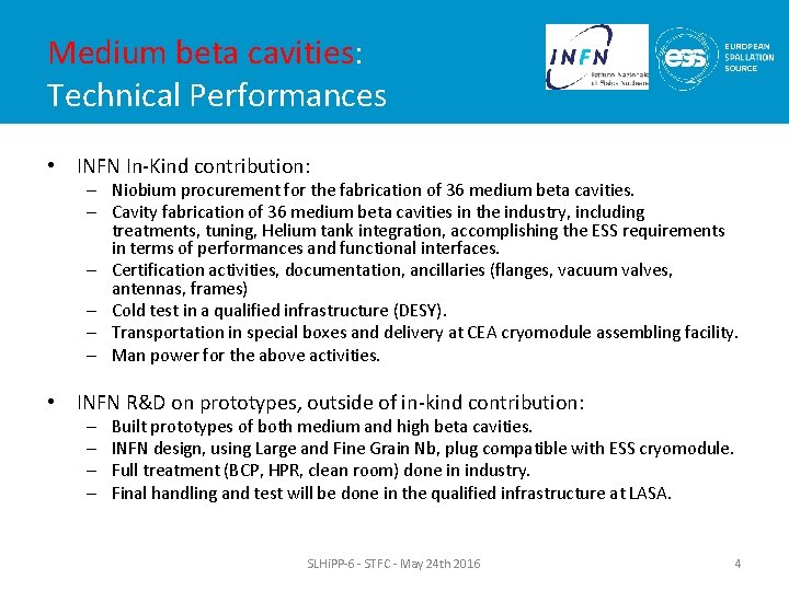
Medium beta cavities: Technical Performances • INFN In-Kind contribution: – Niobium procurement for the fabrication of 36 medium beta cavities. – Cavity fabrication of 36 medium beta cavities in the industry, including treatments, tuning, Helium tank integration, accomplishing the ESS requirements in terms of performances and functional interfaces. – Certification activities, documentation, ancillaries (flanges, vacuum valves, antennas, frames) – Cold test in a qualified infrastructure (DESY). – Transportation in special boxes and delivery at CEA cryomodule assembling facility. – Man power for the above activities. • INFN R&D on prototypes, outside of in-kind contribution: – – Built prototypes of both medium and high beta cavities. INFN design, using Large and Fine Grain Nb, plug compatible with ESS cryomodule. Full treatment (BCP, HPR, clean room) done in industry. Final handling and test will be done in the qualified infrastructure at LASA. SLHi. PP-6 - STFC - May 24 th 2016 4
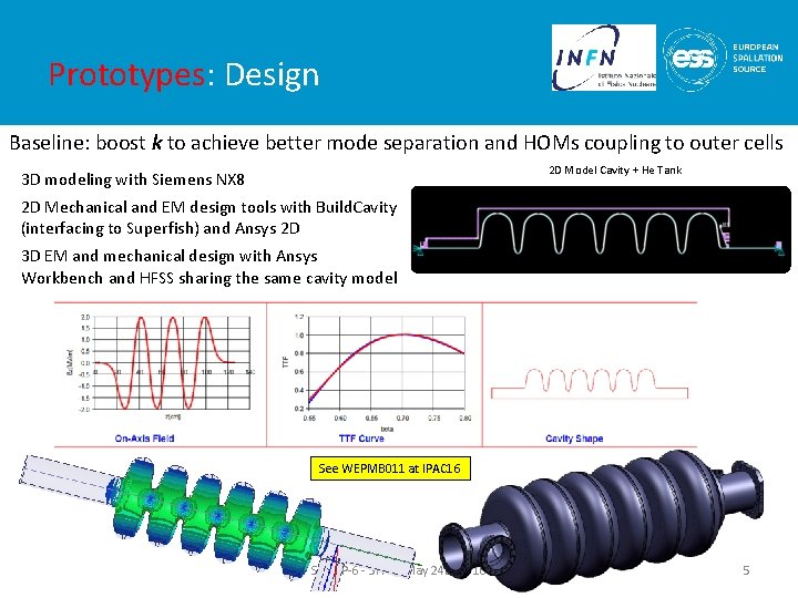
Prototypes: Design Baseline: boost k to achieve better mode separation and HOMs coupling to outer cells 2 D Model Cavity + He Tank 3 D modeling with Siemens NX 8 2 D Mechanical and EM design tools with Build. Cavity (interfacing to Superfish) and Ansys 2 D 3 D EM and mechanical design with Ansys Workbench and HFSS sharing the same cavity model See WEPMB 011 at IPAC 16 SLHi. PP-6 - STFC - May 24 th 2016 5
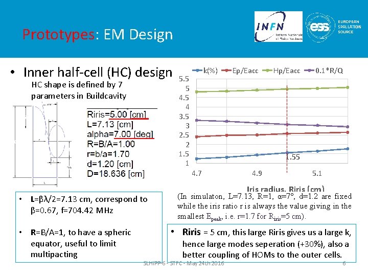
Prototypes: EM Design • Inner half-cell (HC) design HC shape is defined by 7 parameters in Buildcavity k(%) 5. 5 5 4 3. 5 3 2. 5 2 1. 5 1 • R=B/A=1, to have a spheric equator, useful to limit multipacting Hp/Eacc 0. 1*R/Q 1. 55 4. 7 • L=βλ/2=7. 13 cm, correspond to β=0. 67, f=704. 42 MHz Ep/Eacc 4. 9 5. 1 Iris radius, Riris (cm) (In simulaton, L=7. 13, R=1, α=7°, d=1. 2 are fixed while the iris ratio r is always the value giving in the smallest Epeak, i. e. r=1. 7 for Riris=5 cm). • Riris = 5 cm, this large Riris gives us a large k, hence large modes seperation (+30%), also a better coupling of HOMs to the outer cells. SLHi. PP-6 - STFC - May 24 th 2016 6
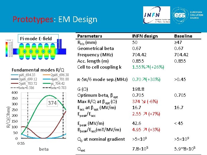
Prototypes: EM Design Pi-mode E-field Fundamental modes R/Q(Ohm) pi/6_694. 35 3 pi/6_699. 12 5 pi/6_703. 72 beta=0. 586 400 350 300 250 200 150 100 50 0 2 pi/6_696. 38 4 pi/6_701. 80 pi_704. 42 beta=0. 783 374 0. 55 beta Parameters Riris (mm) Geometrical beta Frequency (MHz) Acc. length (m) Cell to cell coupling k INFN design 50 0. 67 704. 42 0. 855 1. 55%↗(+26%) Baseline ≥ 47 0. 67 704. 42 0. 855 π-5π/6 mode sep. (MHz) 0. 70↗(+30%) >0. 45 G (Ω) Optimum beta, βopt Max R/Q at βopt (Ω) Eacc at βopt (MV/m) Epeak/Eacc 198. 8 0. 705 374 ↘ (-6%) 16. 7 2. 55 ↗ (+7%) 0. 705 16. 7 Epeak (MV/m) Bpeak/Eacc(m. T/MV/m) 42. 6 4. 95 ↗ (+3%) < 45 Q 0 at nominal gradient >5× 10⁹ Qext 7. 8× 10⁵ 5. 9~8× 10⁵
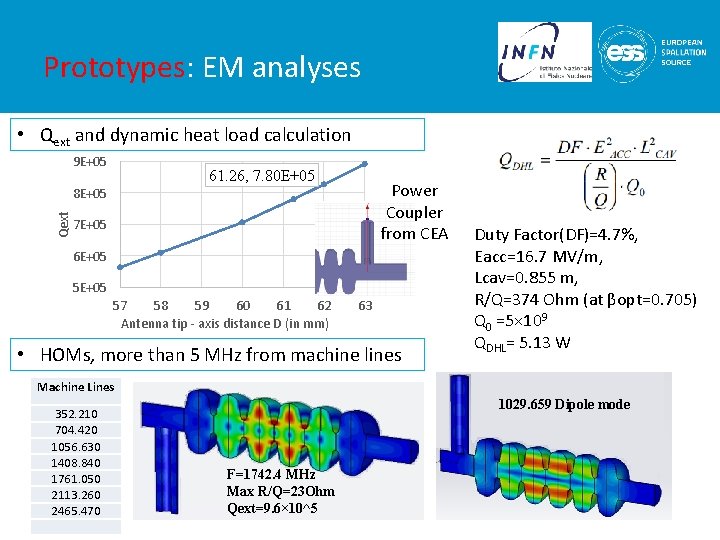
Prototypes: EM analyses • Qext and dynamic heat load calculation 9 E+05 61. 26, 7. 80 E+05 Power Coupler from CEA Qext 8 E+05 7 E+05 6 E+05 57 58 59 60 61 62 Antenna tip - axis distance D (in mm) 63 • HOMs, more than 5 MHz from machine lines Duty Factor(DF)=4. 7%, Eacc=16. 7 MV/m, Lcav=0. 855 m, R/Q=374 Ohm (at βopt=0. 705) Q 0 =5× 10⁹ QDHL= 5. 13 W Machine Lines 352. 210 704. 420 1056. 630 1408. 840 1761. 050 2113. 260 2465. 470 1029. 659 Dipole mode F=1742. 4 MHz Max R/Q=23 Ohm Qext=9. 6× 10^5
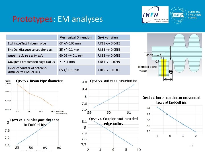
Prototypes: EM analyses Mechanical Dimention Qext variation Etching effect in beam pipe 68 +/- 0. 05 mm 7. 8 E 5 -/+ 0. 04 E 5 End. Cell distance to coupler port 35 +/- 0. 1 mm 7. 8 E 5 +/- 0. 05 E 5 Antenna tip to cavity axis 60. 26 +/- 0. 1 mm 7. 8 E 5 +/- 0. 06 E 5 Coulper port blended edge radius 7 +/- 1 mm 7. 8 E 5 -/+ 0. 07 E 5 Inner conductor of antenna distance to End. Cell iris 85 +/- 0. 1 mm 7. 8 E 5 -/+ 0. 03 E 5 Qext vs. Beam Pipe diameter Qext vs. Antenna penetration Qext vs. Inner conductor movement toward End. Cell iris Qext vs. Coupler port distance to End. Cell iris PDR, Milan, May 2016 Qext vs. Coupler port blended edge radius SLHi. PP-6 - STFC - May 24 th 2016 9
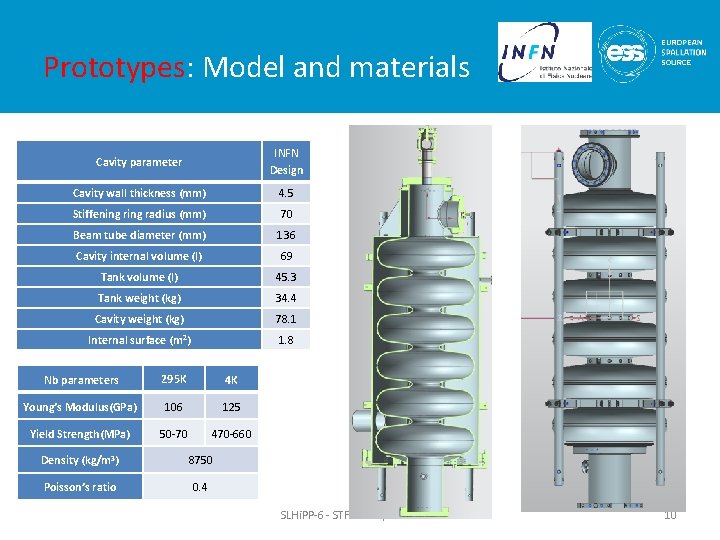
Prototypes: Model and materials Cavity parameter INFN Design Cavity wall thickness (mm) 4. 5 Stiffening radius (mm) 70 Beam tube diameter (mm) 136 Cavity internal volume (l) 69 Tank volume (l) 45. 3 Tank weight (kg) 34. 4 Cavity weight (kg) 78. 1 Internal surface (m 2) 1. 8 Nb parameters 295 K 4 K Young’s Modulus(GPa) 106 125 Yield Strength(MPa) 50 -70 470 -660 Density (kg/m 3) 8750 Poisson’s ratio 0. 4 SLHi. PP-6 - STFC - May 24 th 2016 10
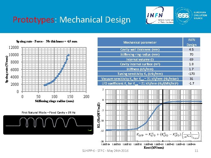
Prototypes: Mechanical Design Spring rate - Force - Nb thickness = 4. 5 mm Mechanical parameter Cavity wall thickness (mm) Stiffening radius (mm) Internal volume (l) Cavity internal surface (m 2) Stiffness (k. N/mm) Tuning sensitivity K T (k. Hz/mm) Vacuum sensitivity KV for Kext ~ 21 k. N/mm (Hz/mbar) LFD coefficient KL for Kext ~ 21 k. N/mm (Hz/(MV/m)2) 10000 8000 6000 4000 2000 5 0 0 50 100 150 200 0 Stiffening rings radius (mm) First Natural Mode – Fixed Cavity = 86 Hz KL (Hz/(MV/m)2) Spring rate (N/mm) 12000 INFN Design 4. 5 70 69 1. 8 1. 7 -170 31 -1. 7 -5 -10 -15 -20 1. 00 E-04 1. 00 E-03 1. 00 E-02 1. 00 E-01 1. 00 E+00 1. 00 E+01 1. 00 E+02 1. 00 E+03 1. 00 E+04 SLHi. PP-6 - STFC - May 24 th 2016 Kext (k. N/mm) 11
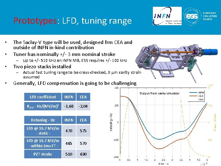
Prototypes: LFD, tuning range • • The Saclay-V type will be used, designed frm CEA and outside of INFN in-kind contribution Tuner has nominally +/- 3 mm nominal stroke – Up to +/- 510 k. Hz on INFN MB, ESS requires +/- 100 k. Hz • Two piezo stacks installed – Actual fast tuning range to be cross-checked, 3 mm cavity strain assumed • Generally, LFD compensation is going to be challenging LFD coefficient INFN CEA KLFD - Hz/(MV/m)2 -1, 68 -2, 04 Detuning - Hz INFN CEA LFD @ 16. 7 MV/m - static - 470 575 LFD @ 16. 7 MV/m - within 3 ms FT - 465 570 PZT stroke 510 630 Output from cavity simulator
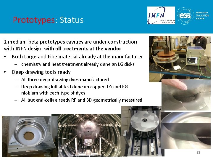
Prototypes: Status 2 medium beta prototypes cavities are under construction with INFN design with all treatments at the vendor • Both Large and Fine material already at the manufacturer – chemistry and heat treatment already done on LG disks • Deep drawing tools ready – All three deep-drawing dyes manufactured – Deep drawing initial test done on copper, LG and FG niobium with each type of dyes – All but end-cells already RF and 3 D geometrically measured SLHi. PP-6 - STFC - May 24 th 2016 13
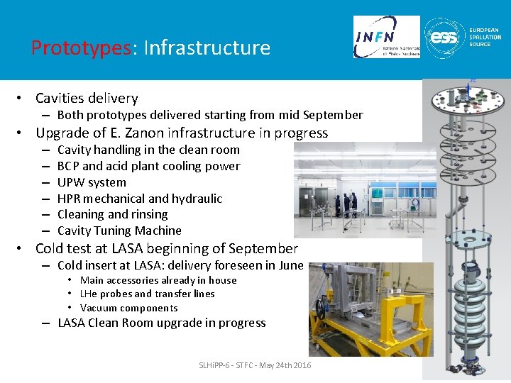
Prototypes: Infrastructure • Cavities delivery – Both prototypes delivered starting from mid September • Upgrade of E. Zanon infrastructure in progress – – – Cavity handling in the clean room BCP and acid plant cooling power UPW system HPR mechanical and hydraulic Cleaning and rinsing Cavity Tuning Machine • Cold test at LASA beginning of September – Cold insert at LASA: delivery foreseen in June • Main accessories already in house • LHe probes and transfer lines • Vacuum components – LASA Clean Room upgrade in progress SLHi. PP-6 - STFC - May 24 th 2016 14
Series: Procurements • Preliminary Design Review last week in Milan – Committee and reviewers were “impressed by both the level of detail of the work and the application of LASA’s previous experience in SRF cavity design and production” and “that the design presented is sufficiently advanced and ready for LASA to proceed detailed design and prototyping”. – The committee recommended to test the medium-beta cavity in the M-ECCTD • Niobium procurement – Specification under definition, starting from the E-XFEL specs, and then reviewed by experts. – Start call for tender procedure within few weeks • Cavity procurement – Technical specification under finalization. All treatments will be charged to the manufacturer in order to have cavities ready for vertical test. – Agreement with DESY for the series cold test under finalization – Start call for tender in summer this year SLHi. PP-6 - STFC - May 24 th 2016 15
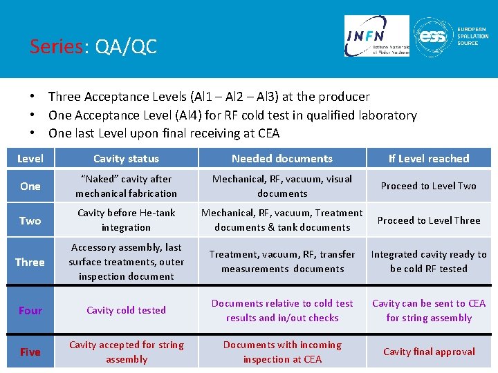
Series: QA/QC • Three Acceptance Levels (Al 1 – Al 2 – Al 3) at the producer • One Acceptance Level (Al 4) for RF cold test in qualified laboratory • One last Level upon final receiving at CEA Level Cavity status Needed documents If Level reached One “Naked” cavity after mechanical fabrication Mechanical, RF, vacuum, visual documents Proceed to Level Two Cavity before He-tank integration Mechanical, RF, vacuum, Treatment documents & tank documents Proceed to Level Three Accessory assembly, last surface treatments, outer inspection document Treatment, vacuum, RF, transfer measurements documents Integrated cavity ready to be cold RF tested Four Cavity cold tested Documents relative to cold test results and in/out checks Cavity can be sent to CEA for string assembly Five Cavity accepted for string assembly Documents with incoming SLHi. PP-6 - STFC - May 24 th 2016 inspection at CEA Cavity final approval 16
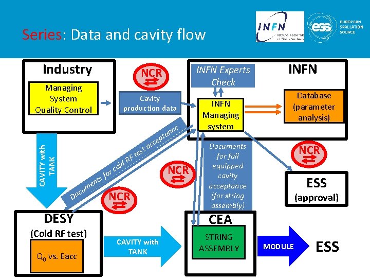
Series: Data and cavity flow Industry INFN Experts Check NCR Managing System Quality Control Cavity production data CAVITY with TANK ce or sf old c RF t tes tan p cce a NCR t n me u oc D DESY (Cold RF test) Q 0 vs. Eacc NCR CAVITY with TANK INFN Managing system INFN Database (parameter analysis) Documents for full equipped cavity acceptance (for string assembly) NCR ESS (approval) CEA STRING ASSEMBLY SLHi. PP-6 - STFC - May 24 th 2016 MODULE ESS 17
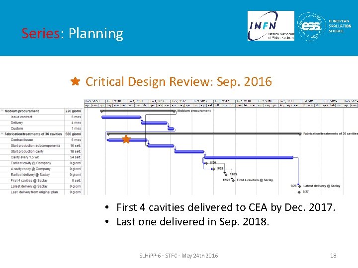
Series: Planning Critical Design Review: Sep. 2016 • First 4 cavities delivered to CEA by Dec. 2017. • Last one delivered in Sep. 2018. SLHi. PP-6 - STFC - May 24 th 2016 18
Medium beta cavities: Summary • Prototypes activity well advanced – EBW of both prototypes in July – First cavity delivered at LASA by mid September 2016 – First cold test results in October 2016, next one within the next month. • Series production strategy under finalization – Procurement process are about ready to start with CFTs – Cold test agreement under finalization with DESY • 2 cavities will be tested in one cooldown, insert design in progress at DESY taking benefits from LASA insert. SLHi. PP-6 - STFC - May 24 th 2016 19
- Slides: 19