
ESM XFP Source Front End Overview for IRR
- Slides: 25
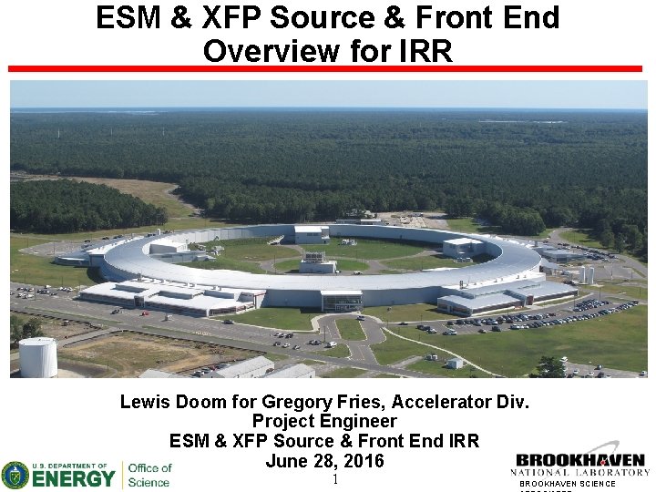
ESM & XFP Source & Front End Overview for IRR Lewis Doom for Gregory Fries, Accelerator Div. Project Engineer ESM & XFP Source & Front End IRR June 28, 2016 1 BROOKHAVEN SCIENCE
Outline • • • Scope Machine Status & Operating Schedule Source Specs, Layouts, Installation & Readiness Insertion Device (ID) Safety Features Front End (FE) Details Differences in Bending Magnet (BM) Front Ends Front End Layouts, Installation & Readiness Radiation Safety Source & FE Commissioning Plan Conclusion 2 BROOKHAVEN SCIENCE
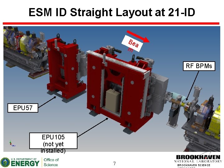
Scope • ESM (21 -ID) Insertion device & straight section: • • • One 1. 4 m EPU 57 One EPU vacuum chamber & RF BPMs Does not include 2. 8 m EPU 105 (not yet installed; separate IRR) XFP (17 -BM) Source • One 3 -pole wiggler (3 PW) ESM Front End: • • Insertion device (ID) front end The photon & safety shutters are wired into PPS & EPS XFP Front End • • • Bending magnet (BM) front end Front end mirror covered in beamline presentation The photon & safety shutters are wired into PPS & EPS 3 BROOKHAVEN SCIENCE
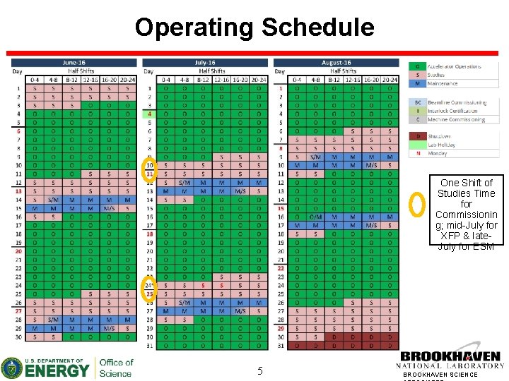
Machine Status & Shutdown Schedule • Installation, testing & commissioning dependent upon • • • operating schedule NSLS-Il beamline operations in process Three machine shutdowns per year (4 -6 weeks each) • • • Dec/Jan April/May Aug/Sept Typically a two-day maintenance period every other week & a studies period every week during operations Minor installation & testing during maintenance days Installation completed during May ‘ 16 shutdown Commissioning scheduled for July ‘ 16 4 BROOKHAVEN SCIENCE
Operating Schedule One Shift of Studies Time for Commissionin g; mid-July for XFP & late. July for ESM 5 BROOKHAVEN SCIENCE
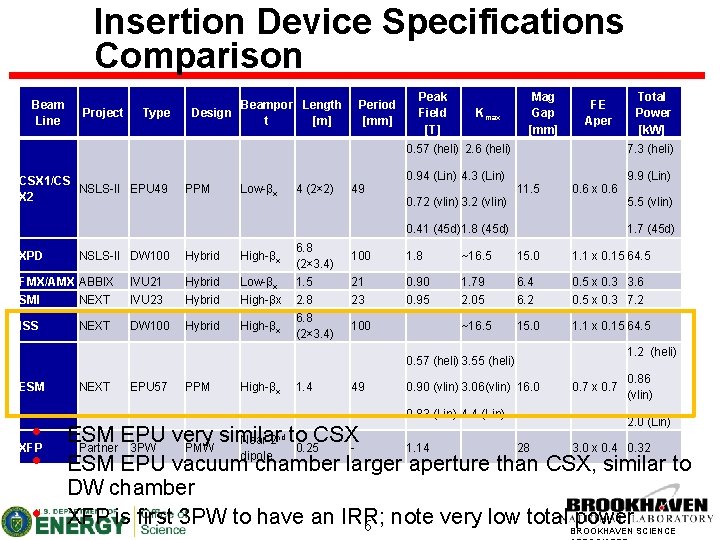
Insertion Device Specifications Comparison Beam Line Project Type CSX 1/CS NSLS-II EPU 49 X 2 Beampor Length Design t [m] PPM Low-βx 4 (2× 2) Period [mm] 49 Peak Field [T] Kmax Mag Gap [mm] FE Aper 0. 57 (heli) 2. 6 (heli) 7. 3 (heli) 0. 94 (Lin) 4. 3 (Lin) 9. 9 (Lin) 0. 72 (vlin) 3. 2 (vlin) 11. 5 0. 6 x 0. 6 0. 41 (45 d) 1. 8 (45 d) XPD NSLS-II DW 100 Hybrid High-βx FMX/AMX ABBIX SMI NEXT IVU 21 IVU 23 Hybrid Low-βx High-βx ISS DW 100 Hybrid High-βx NEXT 6. 8 (2× 3. 4) 1. 5 2. 8 6. 8 (2× 3. 4) • • XFP • NEXT EPU 57 PPM High-βx 1. 4 5. 5 (vlin) 1. 7 (45 d) 100 1. 8 ~16. 5 15. 0 1. 1 x 0. 15 64. 5 21 23 0. 90 0. 95 1. 79 2. 05 6. 4 6. 2 0. 5 x 0. 3 3. 6 0. 5 x 0. 3 7. 2 ~16. 5 15. 0 1. 1 x 0. 15 64. 5 100 1. 2 (heli) 0. 57 (heli) 3. 55 (heli) ESM Total Power [k. W] 49 0. 90 (vlin) 3. 06(vlin) 16. 0 0. 83 (Lin) 4. 4 (Lin) 0. 7 x 0. 7 0. 86 (vlin) 2. 0 (Lin) ESM EPU very similar Near 2 to CSX Partner 3 PW PMW 0. 25 1. 14 28 3. 0 x 0. 4 0. 32 dipole ESM EPU vacuum chamber larger aperture than CSX, similar to DW chamber XFP is first 3 PW to have an IRR; power SCIENCE 6 note very low total BROOKHAVEN nd
ESM ID Straight Layout at 21 -ID Be a m RF BPMs EPU 57 EPU 105 (not yet installed) 7 BROOKHAVEN SCIENCE
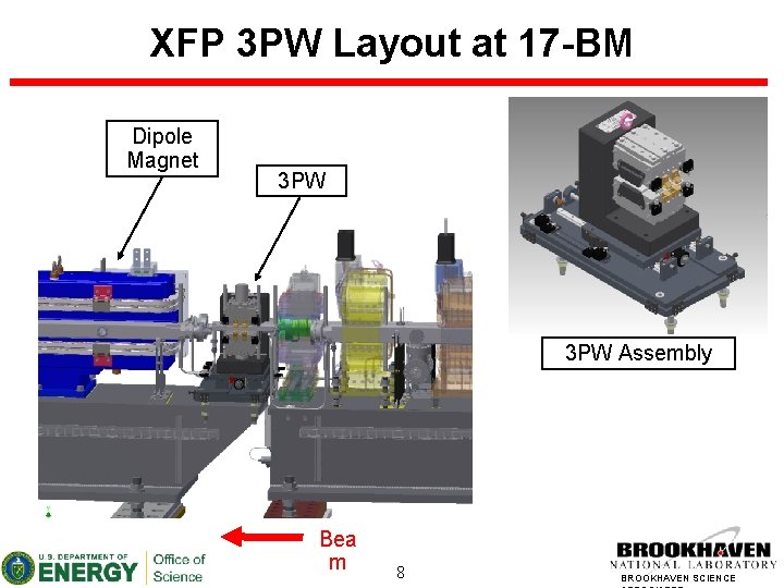
XFP 3 PW Layout at 17 -BM Dipole Magnet 3 PW Assembly Bea m 8 BROOKHAVEN SCIENCE
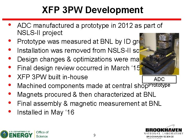
XFP 3 PW Development • • • ADC manufactured a prototype in 2012 as part of NSLS-II project Prototype was measured at BNL by ID group Installation was removed from NSLS-II scope Design changes & optimizations were made Final design review occurred in March ‘ 15 XFP 3 PW built in-house ADC Machined components made at central shop. Prototype Magnets procured & then characterized at BNL Final assembly & magnetic measurement at BNL Installed in May ‘ 16 9 BROOKHAVEN SCIENCE
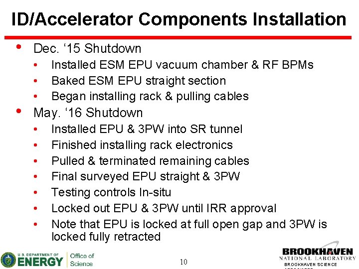
ID/Accelerator Components Installation • • Dec. ‘ 15 Shutdown • • • Installed ESM EPU vacuum chamber & RF BPMs Baked ESM EPU straight section Began installing rack & pulling cables May. ‘ 16 Shutdown • • Installed EPU & 3 PW into SR tunnel Finished installing rack electronics Pulled & terminated remaining cables Final surveyed EPU straight & 3 PW Testing controls In-situ Locked out EPU & 3 PW until IRR approval Note that EPU is locked at full open gap and 3 PW is locked fully retracted 10 BROOKHAVEN SCIENCE
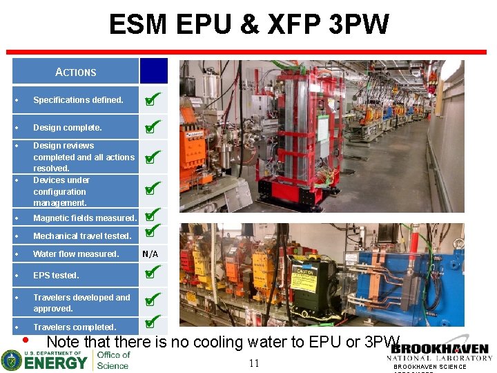
ESM EPU & XFP 3 PW ACTIONS Specifications defined. Design complete. Design reviews completed and all actions resolved. Devices under configuration management. Magnetic fields measured. Mechanical travel tested. Water flow measured. EPS tested. Travelers developed and approved. Travelers completed. • N/A Note that there is no cooling water to EPU or 3 PW 11 BROOKHAVEN SCIENCE
Safety Features of NSLS-II Insertion Devices • Various safety features have been implemented for all IDs: • Brakes in motors – Brakes are on when there is no power • Self-locking gears – Gap will not close by attractive force only (EPU) • Pilot lamp during gap/phase motion (EPU) – Warns people in the vicinity of the device that it is in motion • Lexan cover for magnetic gaps and external pinch points (EPU) – Covers from both inner and outer side of a device. • LOTO procedures during maintenance – Written procedure for each 12 type of the device for lock-out BROOKHAVEN SCIENCE
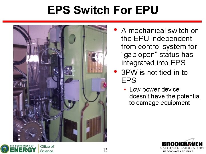
EPS Switch For EPU • • A mechanical switch on the EPU independent from control system for “gap open” status has integrated into EPS 3 PW is not tied-in to EPS • Low power device doesn’t have the potential to damage equipment 13 BROOKHAVEN SCIENCE
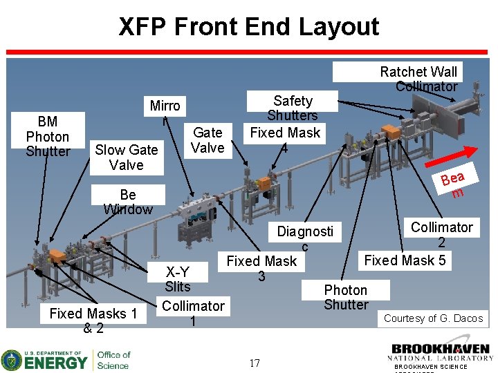
Front End Details • • A front end delivers the photon beam to the beamline while controlling the sizes of both the synchrotron and bremsstrahlung radiation fans. The fixed mask shadows the vacuum chambers of downstream collimators and safety shutters for beam deviations controlled by active interlock. Lead collimators trim the Bremsstrahlung fan exiting to beamlines. Photon shutter is used to stop the photon beam in order to protect the uncooled safety shutters. The safety shutters block the bremsstrahlung radiation from exiting through the ratchet wall collimator chamber opening. The photon shutter & safety shutters are locked out. (Centrally controlled LOTO) ESM is same design as NSLS-II Project, ABBIX, & other NEXT front ends 14 (BM) front end to have an XFP is the first bending magnet BROOKHAVEN SCIENCE
Major Differences in BM front ends • • • Mirror located in front end (beamline component) (not all BM FEs) Additional gate valves to isolate mirror Additional fixed masks to shadow collimators Additional shadow shield for line of sight Slits contain current measuring devices (same x-y stage) Larger aperture Beryllium window isolates SR & BL vacuum (not all BM FEs) Fixed masks, slits, & photon shutter are Cu-Cr-Zr instead of Glidcop New safety shutter design Different diagnostic flag (beamline component) 15 BROOKHAVEN SCIENCE
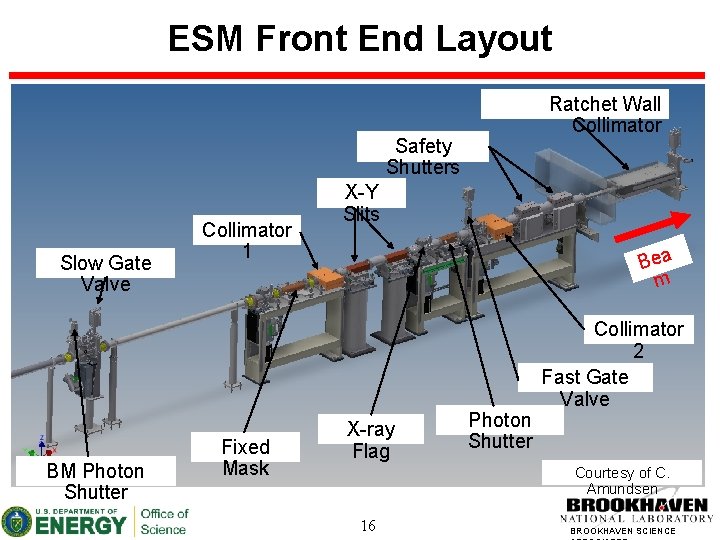
ESM Front End Layout Ratchet Wall Collimator Safety Shutters Slow Gate Valve BM Photon Shutter Collimator 1 Fixed Mask X-Y Slits Bea m X-ray Flag Photon Shutter Collimator 2 Fast Gate Valve Courtesy of C. Amundsen 16 BROOKHAVEN SCIENCE
XFP Front End Layout BM Photon Shutter Mirro r Slow Gate Valve Safety Shutters Fixed Mask 4 Bea m Be Window Fixed Masks 1 &2 Ratchet Wall Collimator Diagnosti 2 c Fixed Mask 5 Fixed Mask X-Y 3 Slits Photon Shutter Collimator Courtesy of G. Dacos 1 17 BROOKHAVEN SCIENCE
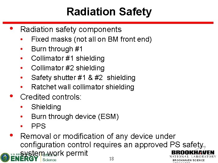
Radiation Safety • • • Radiation safety components • • • Fixed masks (not all on BM front end) Burn through #1 Collimator #1 shielding Collimator #2 shielding Safety shutter #1 & #2 shielding Ratchet wall collimator shielding Credited controls: • • • Shielding Burn through device (ESM) PPS Removal or modification of any device under configuration control requires an approved PS safety system work permit 18 BROOKHAVEN SCIENCE
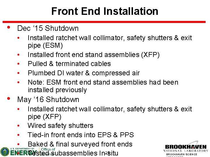
Front End Installation • Dec ‘ 15 Shutdown • • • Installed ratchet wall collimator, safety shutters & exit pipe (ESM) Installed front end stand assemblies (XFP) Pulled & terminated cables Plumbed DI water & compressed air Note: ESM front end stand assemblies had been installed previously May ‘ 16 Shutdown • • • Installed ratchet wall collimator, safety shutters & exit pipe (XFP) Wired safety shutters Tied-in front ends into EPS & PPS Baked & final surveyed front ends 19 Tested subassemblies In-situ BROOKHAVEN SCIENCE
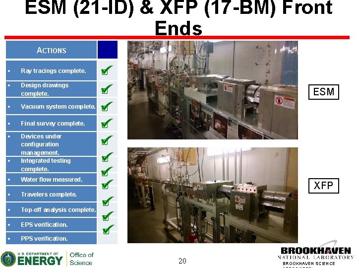
ESM (21 -ID) & XFP (17 -BM) Front Ends ACTIONS Ray tracings complete. Design drawings complete. Vacuum system complete. Final survey complete. Devices under configuration management. Integrated testing complete. Water flow measured. Travelers complete. Top-off analysis complete. EPS verification. PPS verification. ESM XFP 20 BROOKHAVEN SCIENCE
Commissioning Plan • • Commissioning scheduled for mid-July ‘ 16 for XFP & late-July ‘ 16 for ESM Machine studies time reserved Commissioning effort will include staff from Operations, Physics, Insertion Device, Front End, and Diag. groups Software controls & tools already developed and verified during NSLS-II beamline commissioning Procedures released for ID & FE commissioning sequence and radiation survey plan ESM FE same design at NSLS-II Project, ABBIX, & other NEXT ESM EPU similar design to CSX beamline XFP is first BM front end &21 3 PW to be commissioned BROOKHAVEN SCIENCE
Insertion Device Commissioning • • Beam current below 2 m. A Verify orbit and characterize/correct lattice Reduce ID gap (EPU) Generate orbit correction feed-forward (lookup) table Inject with ID gap closed, improve injection efficiency (EPU) General radiation survey Authorization proceed to FE commissioning Note that 3 PW has no gap to close; above process takes place with 3 PW inserted 22 BROOKHAVEN SCIENCE
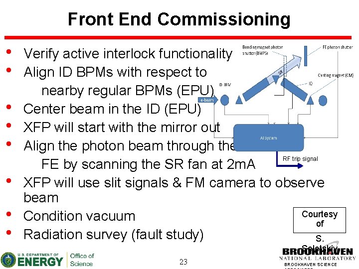
Front End Commissioning • • Verify active interlock functionality Align ID BPMs with respect to nearby regular BPMs (EPU) Center beam in the ID (EPU) XFP will start with the mirror out Align the photon beam through the RF trip signal FE by scanning the SR fan at 2 m. A XFP will use slit signals & FM camera to observe beam Courtesy Condition vacuum of Radiation survey (fault study) S. Seletskiy 23 BROOKHAVEN SCIENCE
Beam Current Increase Plan • • • Obtain authorization to increase current to 85 m. A Close all ID gaps and lock out FE shutters Evaluate and record current machine state Gradually increase current Verify active interlock system being engaged Monitor and verify orbit, tunes, lattice, vacuum, temperature Hold Point – Radiation survey • • Phase 1 (slits open) Phase 2 (slits closed) XFP Phase 2 a (mirror out); Phase 2 b (mirror in, slits open) Phase 3 (fault studies) Beam conditioning Repeat to allowable current 24 BROOKHAVEN SCIENCE
Conclusion • • ESM EPU, XFP 3 PW and both front ends installed & tested Radiation components under configuration control Assembly drawings, ray tracings, procedures, & travelers are available Photon shutter & safety shutters are locked in the down position EPU & 3 PW are locked out until commissioning starts ESM EPU, XFP 3 PW and both front ends are ready for commissioning No self-identified pre-starts Commissioning experience & prepared commissioning procedures from NSLS-II Project, ABBIX, & NEXT 25 BROOKHAVEN SCIENCE