ESIS KRION6 T beam emittance measurement device Dr

ESIS KRION-6 T beam emittance measurement device Dr. E. D. DONETS, Dr. E. E. DONETS, Dr. GORBUNOV N. V. , Eng. DONETS D. E. , Eng. PONKIN D. O. , RAMSDORF A. Yu. , BOYTSOV A. Yu NEC 2015, Montenegro, Budva ponkin@jinr. ru

Heavy ion source KRION-6 T is one of the main part of NICA/MPD injection complex. KRION-6 T AT THE TEST BENCH Ponkin Dmitriy 2

The Electron String Ion Source KRION-6 T The KRION-6 T is the new electron string ion source (ESIS) designed to produce beams of highly charged heavy ions. KRION-6 T operation is based on step by step ionization of the ions by hitting with electrons of the electron string. The main task is to produce the Au 32+ ions for the NICA/MPD project. KRION-6 T ion source has effective electron string current density up to 1600 A/cm 2. Ponkin Dmitriy 3

KRION-6 T at the 50 th NUCLOTRON run Was used to produce Ar 16+ ions. KRION-6 T on the HV platform of LU-20 Ponkin Dmitriy 4

Ion beam profile measurements The charged-particle beam precipitation on the ion collector causes the ion current I flow. Charge measurements: Integration time ≈ 10 us VACUUM DDC 316 IC Ion beam Ion collector MCU Ponkin Dmitriy 5

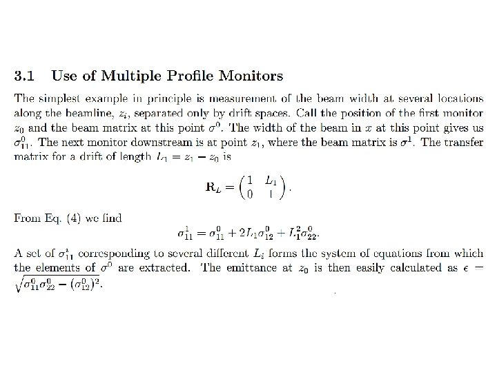
Emittance measurements using of multiple beam profiles DDC 316 IC Ion collector Beam profilometer STEP 1 KRION 6 T Beam extraction line Ion beam Beam Profilometer position 1 Z Ponkin Dmitriy 6

Emittance measurements using of multiple beam profiles DDC 316 IC Ion collector Beam profilometer STEP 2 KRION 6 T Beam extraction line Ion beam Beam Profilometer position 2 Z Ponkin Dmitriy 7

Emittance measurements using of multiple beam profiles DDC 316 IC Ion collector Beam profilometer STEP 3 KRION 6 T Beam extraction line Ion beam Beam Profilometer position 3 Z Ponkin Dmitriy 8

Emittance measurements using of multiple beam profiles Beam Profile 1 Beam Profile 2 Beam emittance calculation Beam Profile 3 Ponkin Dmitriy 9

TI DDC 316 charge to digital converter IC 16 -Channel, Current-Input IC • FULL-SCALE : 3 p. C to 12 p. C • Data Rate Up To 100 k. SPS • Minimum Integration time 10 µs Ponkin Dmitriy 10

Charge to digital converter test PCB AFE schematic Ponkin Dmitriy 11

Ponkin Dmitriy 12

Ceramic beam profilometer • Size: 30 x 30 mm • Number of strips: 21 + 21 = 42 • Spatial resolution: 0, 5 mm • 10 – 20 nkl Ponkin Dmitriy 13

Final device PCB Ponkin Dmitriy 14
 The experiment preparation is in progress 2) The developed")
Status of the work 1) The experiment preparation is in progress 2) The developed electronics test were carried out 3) Beam profile visualization PC software is developing Ponkin Dmitriy 15

Thank you!

Min input current 0, 3 p. A

The ions are confined in the ion trap by radial potential well of the electron string and axial potential barriers on the drift tubes.

The electrodes system of the KRION-6 T is shown on the Fig. 1. The electron gun is placed in the right part of the scheme and consists from: EM –emitter, FC – false cathode and Agun – the anode. The electron gun produces the pulsed electron beam of 10 m. A with the energy up to 10 ke. V. The electron reflector is shown in the left part of the scheme. REF – the reflector itself, Aref – the anode. The ion trap consists from 25 drift tubes and is placed between the electron gun and the electron reflector. EX – the ions extraction electrode.
- Slides: 20