
EqualizationCompensation of Transmission Media Channel copper or fiber
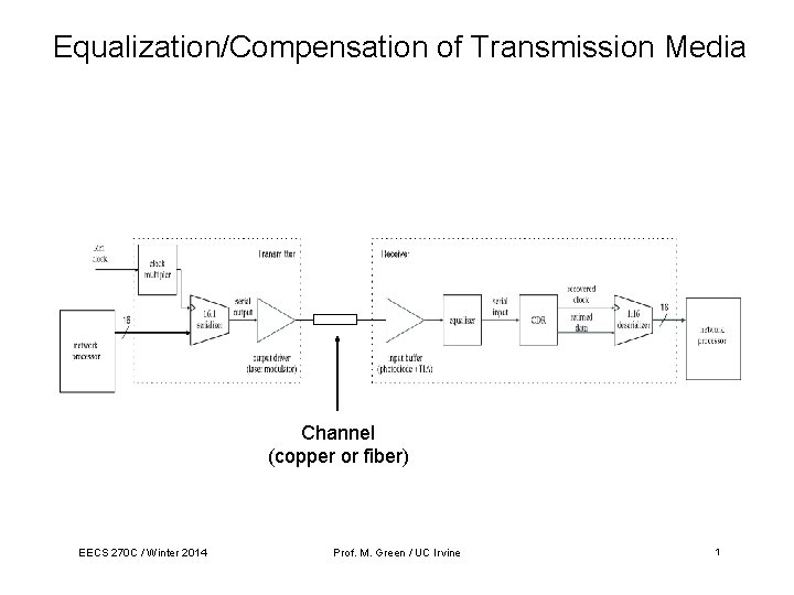
Equalization/Compensation of Transmission Media Channel (copper or fiber) EECS 270 C / Winter 2014 Prof. M. Green / UC Irvine 1
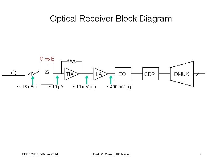
Optical Receiver Block Diagram O E TIA ≈ -18 d. Bm ≈ 10 µA EECS 270 C / Winter 2014 LA ≈ 10 m. V p-p EQ CDR DMUX ≈ 400 m. V p-p Prof. M. Green / UC Irvine 2
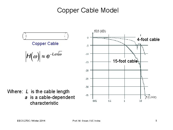
Copper Cable Model 4 -foot cable Copper Cable 15 -foot cable Where: L is the cable length a is a cable-dependent characteristic EECS 270 C / Winter 2014 Prof. M. Green / UC Irvine 2
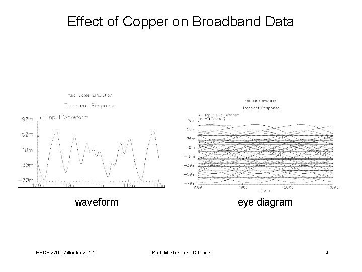
Effect of Copper on Broadband Data waveform EECS 270 C / Winter 2014 eye diagram Prof. M. Green / UC Irvine 3
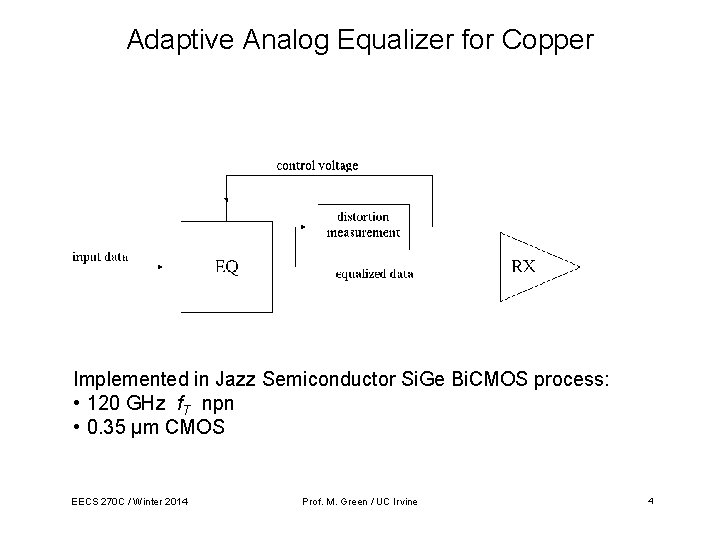
Adaptive Analog Equalizer for Copper Implemented in Jazz Semiconductor Si. Ge Bi. CMOS process: • 120 GHz f. T npn • 0. 35 µm CMOS EECS 270 C / Winter 2014 Prof. M. Green / UC Irvine 4
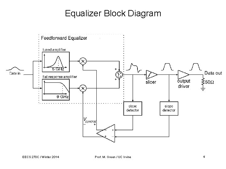
Equalizer Block Diagram EECS 270 C / Winter 2014 Prof. M. Green / UC Irvine 5
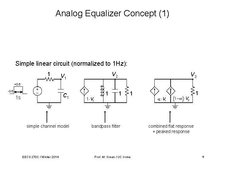
Analog Equalizer Concept (1) Simple linear circuit (normalized to 1 Hz): 1 V 2 V 1 V 3 +0. 5 -0. 5 C 1 1 s simple channel model EECS 270 C / Winter 2014 1 1 bandpass filter Prof. M. Green / UC Irvine combined flat response + peaked response 6
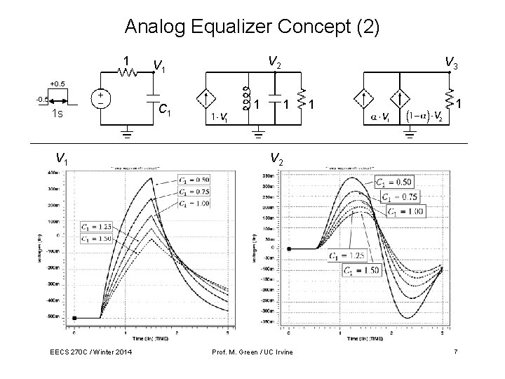
Analog Equalizer Concept (2) 1 V 2 V 1 V 3 +0. 5 -0. 5 1 s V 1 EECS 270 C / Winter 2014 C 1 1 1 V 2 Prof. M. Green / UC Irvine 7
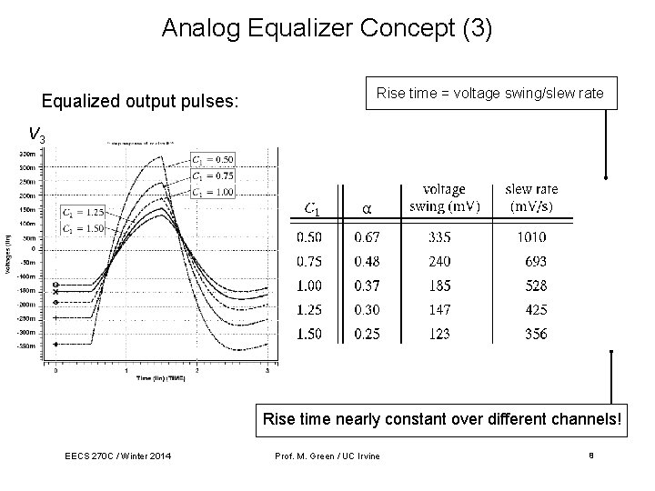
Analog Equalizer Concept (3) Equalized output pulses: Rise time = voltage swing/slew rate V 3 Rise time nearly constant over different channels! EECS 270 C / Winter 2014 Prof. M. Green / UC Irvine 8
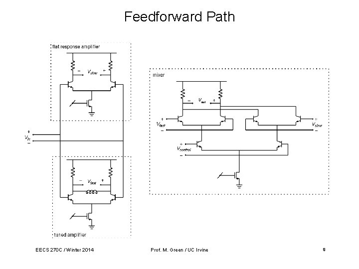
Feedforward Path Vout EECS 270 C / Winter 2014 Prof. M. Green / UC Irvine 9
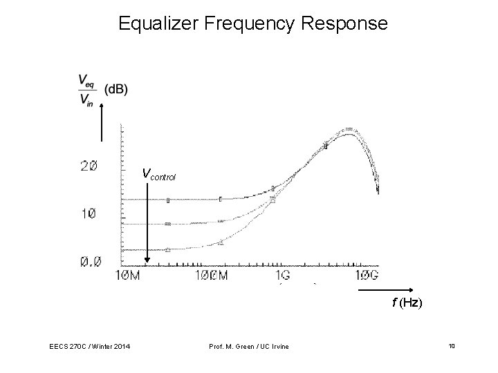
Equalizer Frequency Response Vcontrol f (Hz) EECS 270 C / Winter 2014 Prof. M. Green / UC Irvine 10
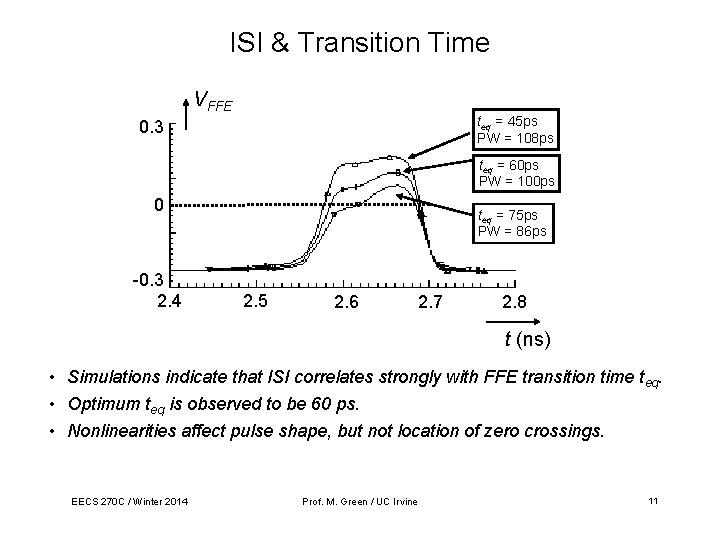
ISI & Transition Time VFFE teq = 45 ps PW = 108 ps 0. 3 teq = 60 ps PW = 100 ps 0 -0. 3 2. 4 teq = 75 ps PW = 86 ps 2. 5 2. 6 2. 7 2. 8 t (ns) • Simulations indicate that ISI correlates strongly with FFE transition time teq. • Optimum teq is observed to be 60 ps. • Nonlinearities affect pulse shape, but not location of zero crossings. EECS 270 C / Winter 2014 Prof. M. Green / UC Irvine 11
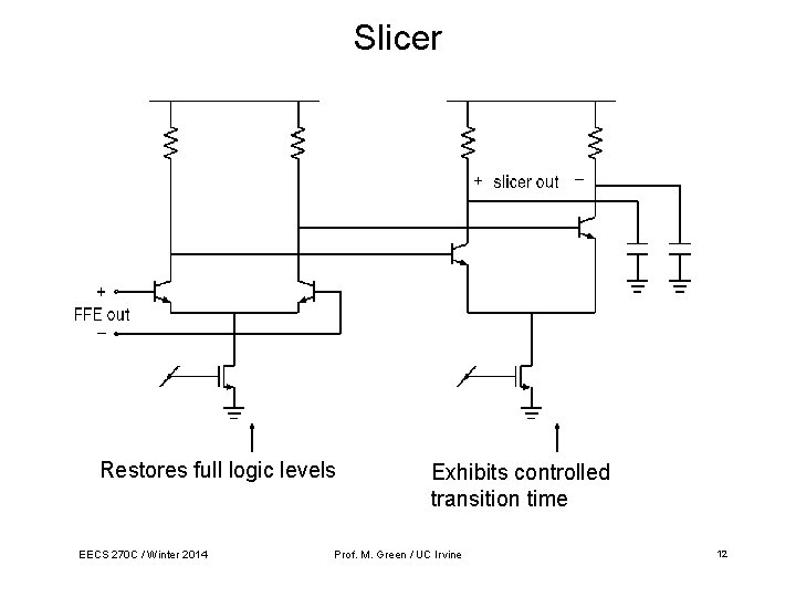
Slicer Restores full logic levels EECS 270 C / Winter 2014 Exhibits controlled transition time Prof. M. Green / UC Irvine 12
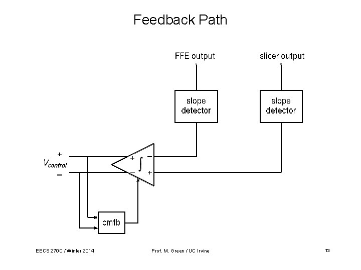
Feedback Path EECS 270 C / Winter 2014 Prof. M. Green / UC Irvine 13
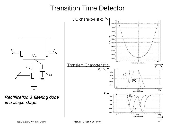
Transition Time Detector DC characteristic: V+ VVS Transient Characteristic: ISS CSS (b) (a) (b) Rectification & filtering done in a single stage. (a) EECS 270 C / Winter 2014 Prof. M. Green / UC Irvine 14 t
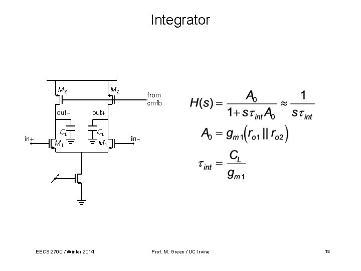
Integrator EECS 270 C / Winter 2014 Prof. M. Green / UC Irvine 15
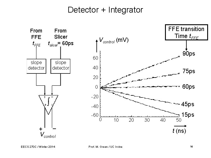
Detector + Integrator From FFE t. FFE slope detector From Slicer tslicer= 60 ps slope detector FFE transition Time t. FFE Vcontrol (m. V) 90 ps 60 40 75 ps 20 60 ps 0 -20 _ + Vcontrol EECS 270 C / Winter 2014 -40 45 ps -60 15 ps 0 10 20 30 40 50 t (ns) Prof. M. Green / UC Irvine 16
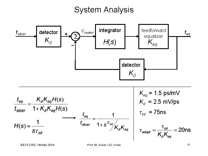
System Analysis tslicer detector Kd Vcontrol + _ integrator feedforward equalizer H(s) teq Keq detector Kd Keq = 1. 5 ps/m. V Kd = 2. 5 m. V/ps int = 75 ns EECS 270 C / Winter 2014 Prof. M. Green / UC Irvine 17
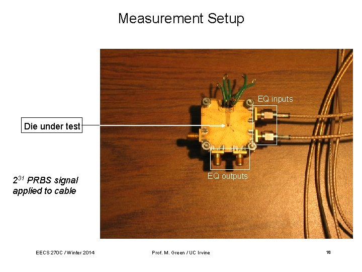
Measurement Setup EQ inputs Die under test 231 PRBS signal applied to cable EECS 270 C / Winter 2014 EQ outputs Prof. M. Green / UC Irvine 18
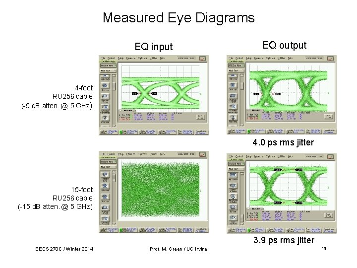
Measured Eye Diagrams EQ input EQ output 4 -foot RU 256 cable (-5 d. B atten. @ 5 GHz) 4. 0 ps rms jitter 15 -foot RU 256 cable (-15 d. B atten. @ 5 GHz) 3. 9 ps rms jitter EECS 270 C / Winter 2014 Prof. M. Green / UC Irvine 19
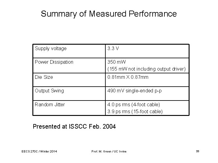
Summary of Measured Performance Supply voltage 3. 3 V Power Dissipation 350 m. W (155 m. W not including output driver) Die Size 0. 81 mm X 0. 87 mm Output Swing 490 m. V single-ended p-p Random Jitter 4. 0 ps rms (4 -foot cable) 3. 9 ps rms (15 -foot cable) Presented at ISSCC Feb. 2004 EECS 270 C / Winter 2014 Prof. M. Green / UC Irvine 20
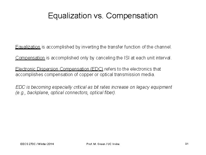
Equalization vs. Compensation Equalization is accomplished by inverting the transfer function of the channel. Compensation is accomplished only by canceling the ISI at each unit interval. Electronic Dispersion Compensation (EDC) refers to the electronics that accomplishes compensation of copper or optical transmission media. EDC is becoming especially critical as bit rates increase on legacy equipment (e. g. , backplane, optical connectors, optical fiber). EECS 270 C / Winter 2014 Prof. M. Green / UC Irvine 21
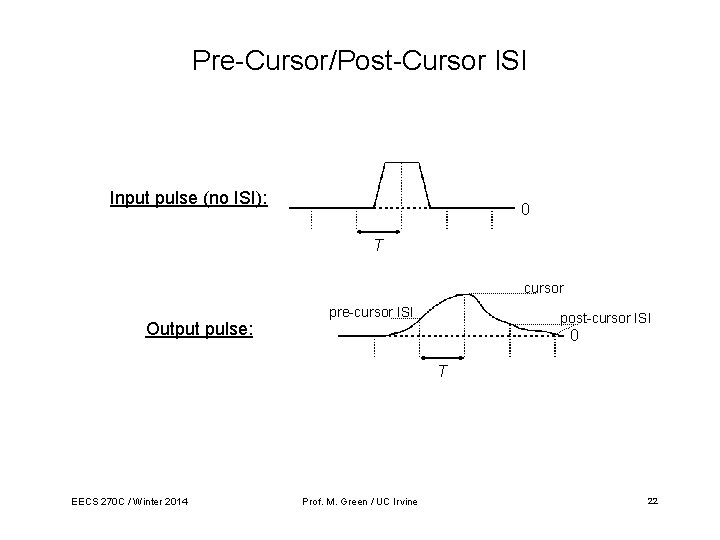
Pre-Cursor/Post-Cursor ISI Input pulse (no ISI): 0 T cursor Output pulse: pre-cursor ISI post-cursor ISI 0 T EECS 270 C / Winter 2014 Prof. M. Green / UC Irvine 22
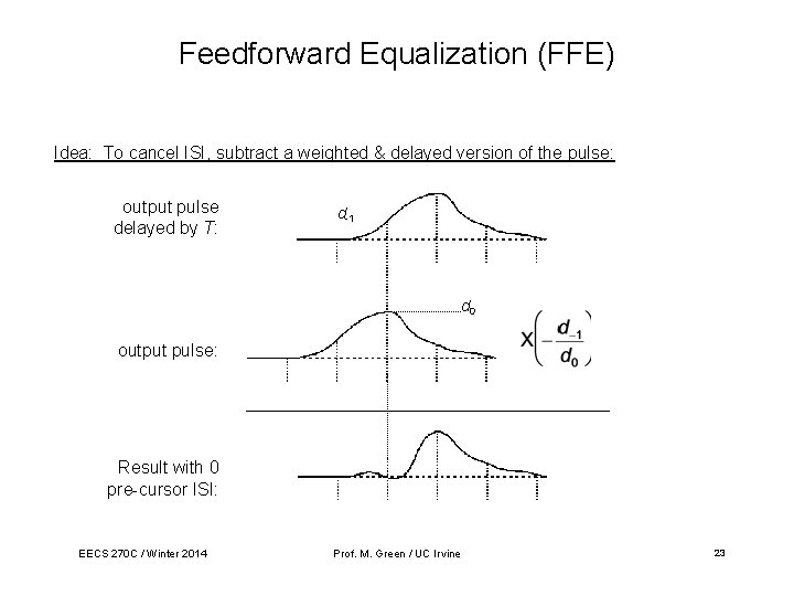
Feedforward Equalization (FFE) Idea: To cancel ISI, subtract a weighted & delayed version of the pulse: output pulse delayed by T: d-1 d 0 output pulse: Result with 0 pre-cursor ISI: EECS 270 C / Winter 2014 Prof. M. Green / UC Irvine 23
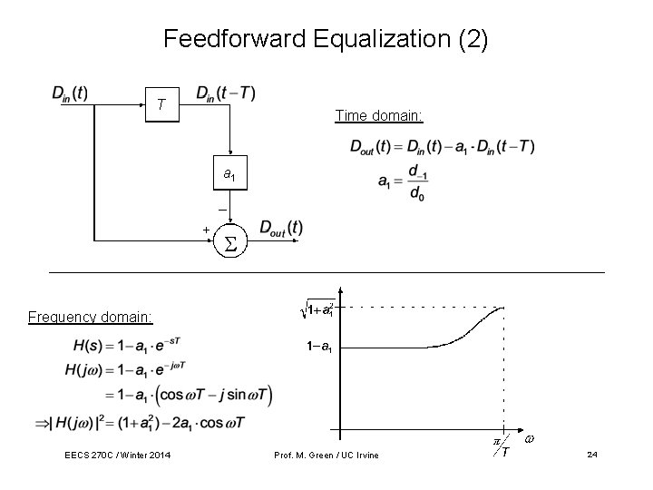
Feedforward Equalization (2) T Time domain: a 1 _ + Frequency domain: EECS 270 C / Winter 2014 Prof. M. Green / UC Irvine 24
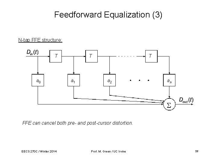
Feedforward Equalization (3) N-tap FFE structure: T a 0 T a 1 T a 2 an FFE cancel both pre- and post-cursor distortion. EECS 270 C / Winter 2014 Prof. M. Green / UC Irvine 25
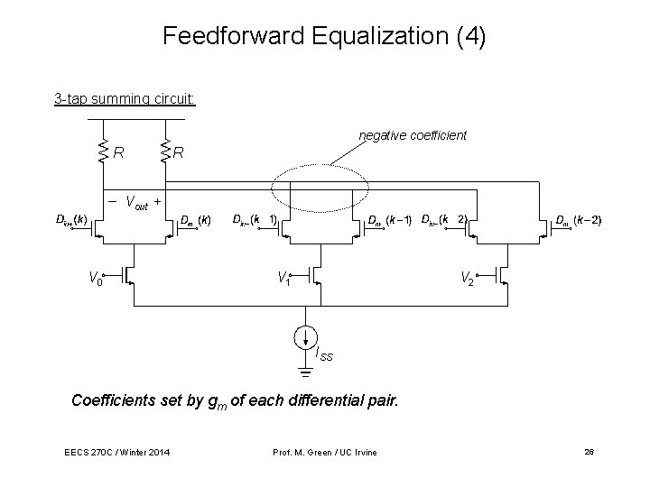
Feedforward Equalization (4) 3 -tap summing circuit: negative coefficient R _ R Vout + V 0 V 1 V 2 ISS Coefficients set by gm of each differential pair. EECS 270 C / Winter 2014 Prof. M. Green / UC Irvine 26
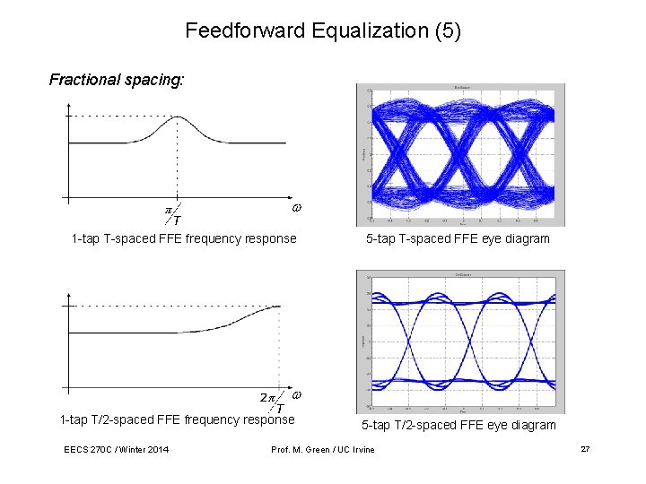
Feedforward Equalization (5) Fractional spacing: 1 -tap T-spaced FFE frequency response 5 -tap T-spaced FFE eye diagram 1 -tap T/2 -spaced FFE frequency response EECS 270 C / Winter 2014 5 -tap T/2 -spaced FFE eye diagram Prof. M. Green / UC Irvine 27
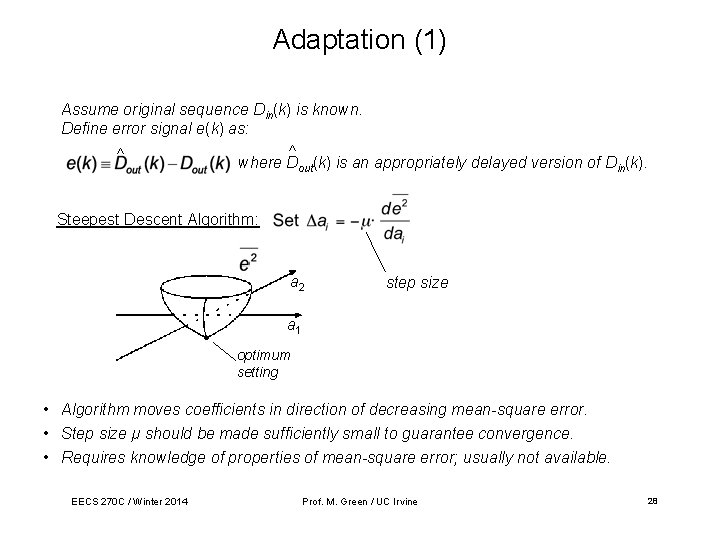
Adaptation (1) Assume original sequence Din(k) is known. Define error signal e(k) as: ^ ^ where Dout(k) is an appropriately delayed version of Din(k). Steepest Descent Algorithm: a 2 step size a 1 optimum setting • Algorithm moves coefficients in direction of decreasing mean-square error. • Step size µ should be made sufficiently small to guarantee convergence. • Requires knowledge of properties of mean-square error; usually not available. EECS 270 C / Winter 2014 Prof. M. Green / UC Irvine 28
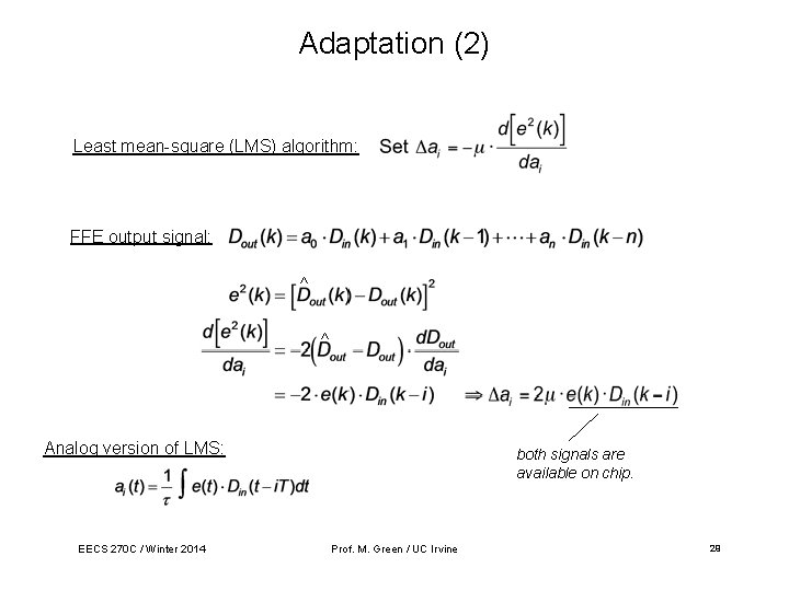
Adaptation (2) Least mean-square (LMS) algorithm: FFE output signal: ^ ^ Analog version of LMS: EECS 270 C / Winter 2014 both signals are available on chip. Prof. M. Green / UC Irvine 29
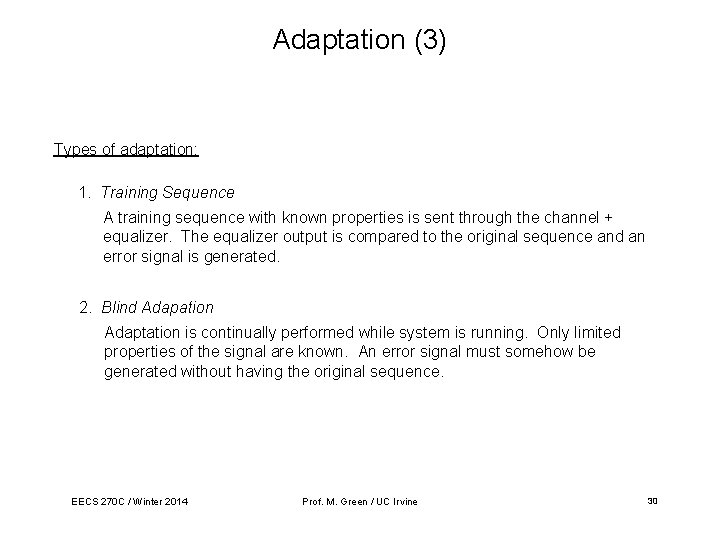
Adaptation (3) Types of adaptation: 1. Training Sequence A training sequence with known properties is sent through the channel + equalizer. The equalizer output is compared to the original sequence and an error signal is generated. 2. Blind Adapation Adaptation is continually performed while system is running. Only limited properties of the signal are known. An error signal must somehow be generated without having the original sequence. EECS 270 C / Winter 2014 Prof. M. Green / UC Irvine 30
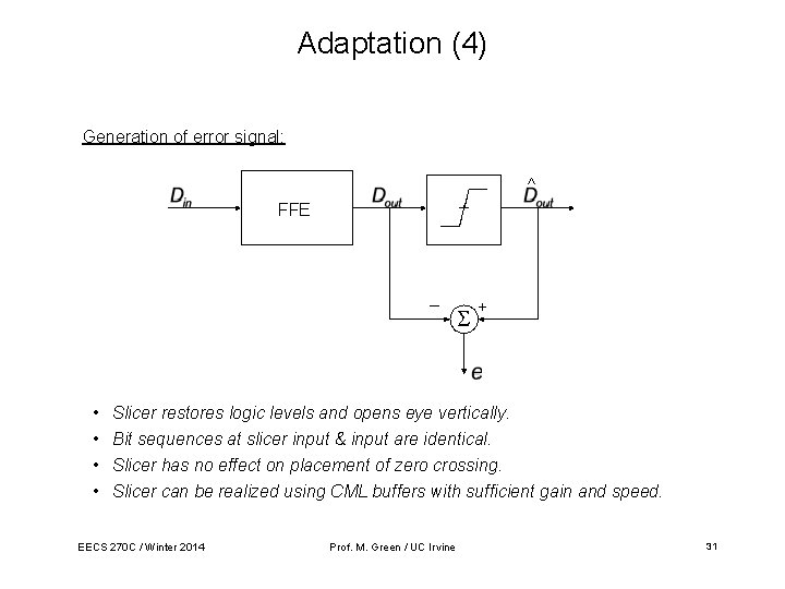
Adaptation (4) Generation of error signal: ^ FFE _ • • + Slicer restores logic levels and opens eye vertically. Bit sequences at slicer input & input are identical. Slicer has no effect on placement of zero crossing. Slicer can be realized using CML buffers with sufficient gain and speed. EECS 270 C / Winter 2014 Prof. M. Green / UC Irvine 31
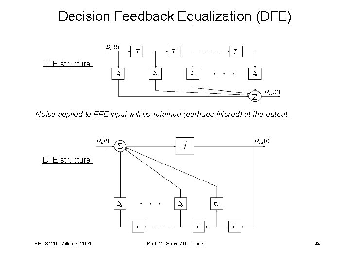
Decision Feedback Equalization (DFE) T T T FFE structure: a 0 a 1 a 2 an Noise applied to FFE input will be retained (perhaps filtered) at the output. DFE structure: + - - bm b 2 T EECS 270 C / Winter 2014 b 1 T Prof. M. Green / UC Irvine T 32
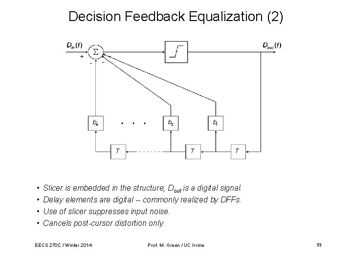
Decision Feedback Equalization (2) + - - - bm b 2 T • • b 1 T T Slicer is embedded in the structure; Dout is a digital signal. Delay elements are digital -- commonly realized by DFFs. Use of slicer suppresses input noise. Cancels post-cursor distortion only. EECS 270 C / Winter 2014 Prof. M. Green / UC Irvine 33
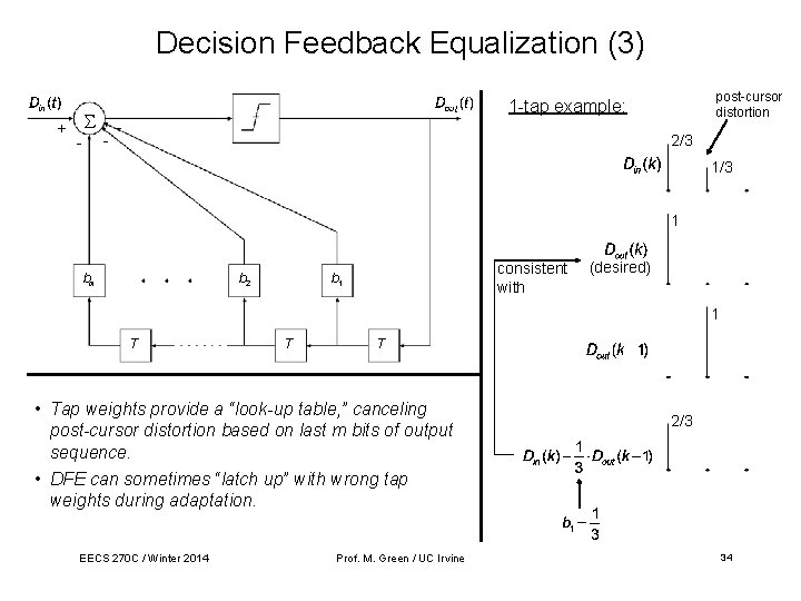
Decision Feedback Equalization (3) post-cursor distortion 1 -tap example: + - - 2/3 1 bm b 2 consistent with b 1 (desired) 1 T T T • Tap weights provide a “look-up table, ” canceling post-cursor distortion based on last m bits of output sequence. • DFE can sometimes “latch up” with wrong tap weights during adaptation. EECS 270 C / Winter 2014 Prof. M. Green / UC Irvine 2/3 34
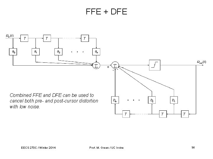
FFE + DFE T a 0 T a 1 T a 2 an Combined FFE and DFE can be used to cancel both pre- and post-cursor distortion with low noise. + - - bm b 2 T EECS 270 C / Winter 2014 Prof. M. Green / UC Irvine b 1 T T 35
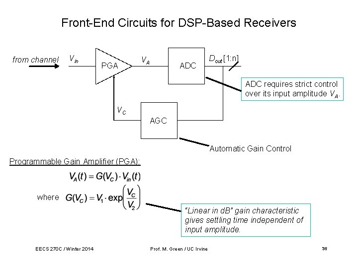
Front-End Circuits for DSP-Based Receivers from channel Vin PGA VA ADC Dout [1: n] ADC requires strict control over its input amplitude VA. VC AGC Automatic Gain Control Programmable Gain Amplifier (PGA): where “Linear in d. B” gain characteristic gives settling time independent of input amplitude. EECS 270 C / Winter 2014 Prof. M. Green / UC Irvine 36
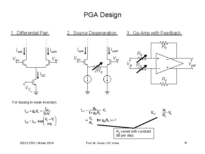
PGA Design 1. Differential Pair: Iout- 2. Source Degeneration: Iout+ Vin. ISS Iout- Iout+ Vin 2 RS 3. Op-Amp with Feedback: Rf RS + V_in RS + V_out Rf + VC_ For biasing in weak inversion: RS varied with constant d. B per step. EECS 270 C / Winter 2014 Prof. M. Green / UC Irvine 37
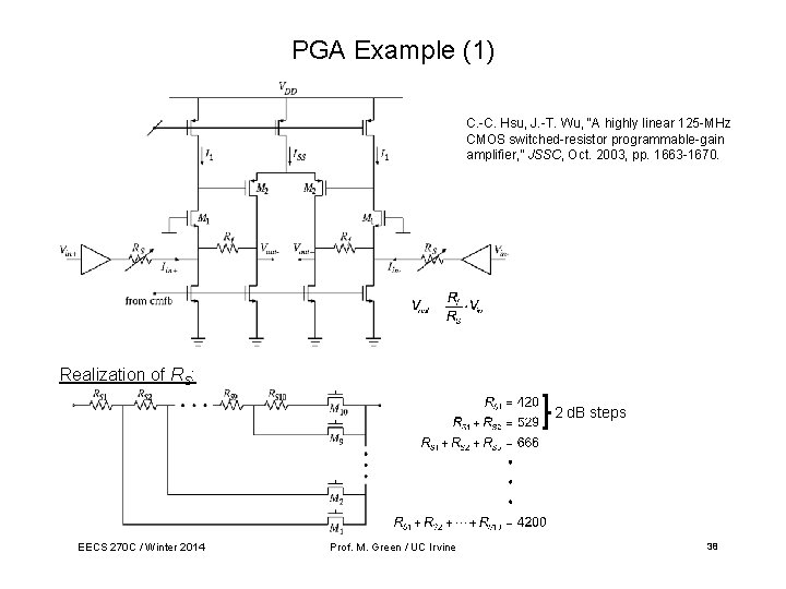
PGA Example (1) C. -C. Hsu, J. -T. Wu, “A highly linear 125 -MHz CMOS switched-resistor programmable-gain amplifier, ” JSSC, Oct. 2003, pp. 1663 -1670. Realization of RS: 2 d. B steps EECS 270 C / Winter 2014 Prof. M. Green / UC Irvine 38
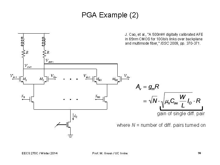
PGA Example (2) J. Cao, et al. , “A 500 m. W digitally calibrated AFE in 65 nm CMOS for 10 Gb/s links over backplane and multimode fiber, ” ISSC 2009, pp. 370 -371. gain of single diff. pair where N = number of diff. pairs turned on EECS 270 C / Winter 2014 Prof. M. Green / UC Irvine 39
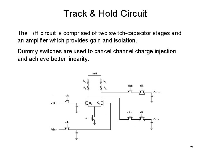
Track & Hold Circuit The T/H circuit is comprised of two switch-capacitor stages and an amplifier which provides gain and isolation. Dummy switches are used to cancel channel charge injection and achieve better linearity. 40
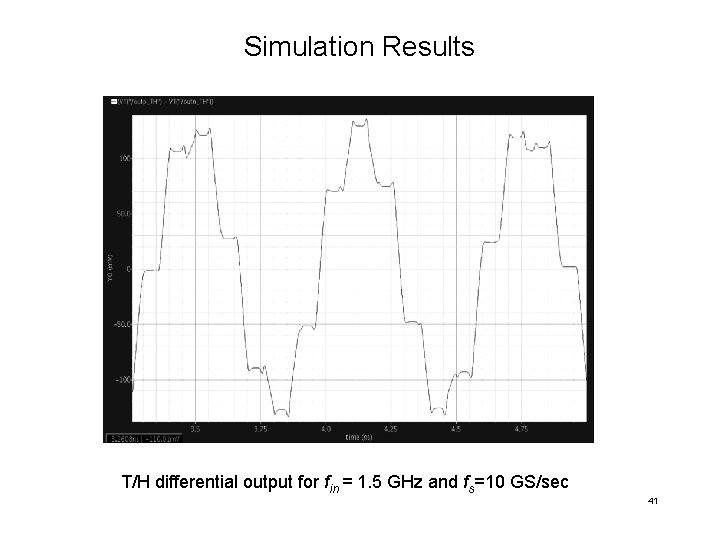
Simulation Results T/H differential output for fin = 1. 5 GHz and fs=10 GS/sec 41
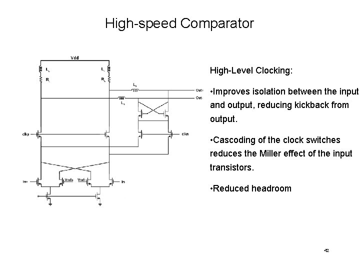
High-speed Comparator High-Level Clocking: • Improves isolation between the input and output, reducing kickback from output. • Cascoding of the clock switches reduces the Miller effect of the input transistors. • Reduced headroom 42
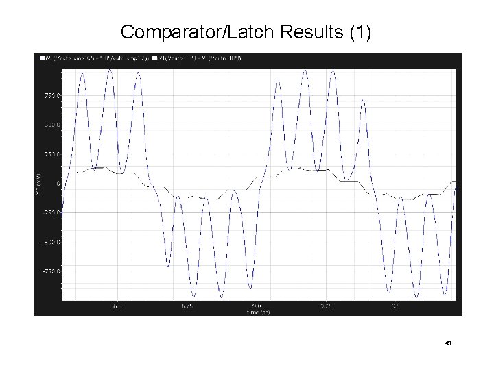
Comparator/Latch Results (1) 43
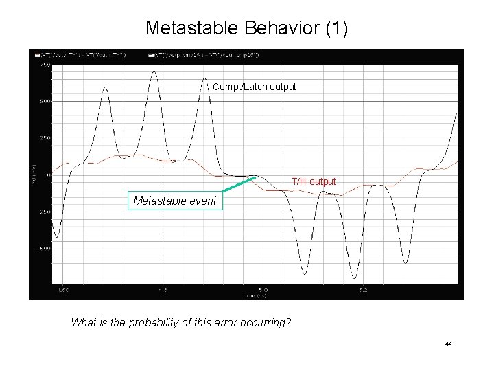
Metastable Behavior (1) Comp. /Latch output T/H output Metastable event What is the probability of this error occurring? 44
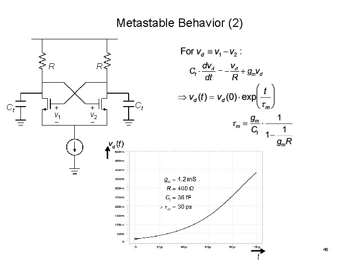
Metastable Behavior (2) R Ct R + v 1 − + v 2 − Ct t 45
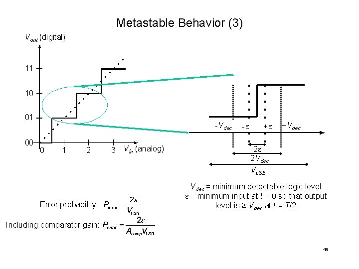
Metastable Behavior (3) Vout (digital) 11 10 01 00 -Vdec 0 1 2 Error probability: 3 Vin (analog) -e +e +Vdec 2 e 2 Vdec VLSB Vdec = minimum detectable logic level e = minimum input at t = 0 so that output level is ≥ Vdec at t = T/2 Including comparator gain: 46
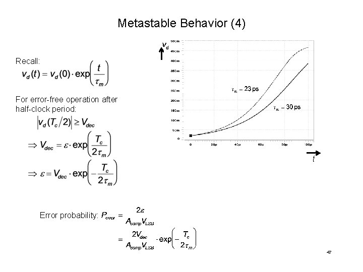
Metastable Behavior (4) Recall: For error-free operation after half-clock period: t Error probability: 47
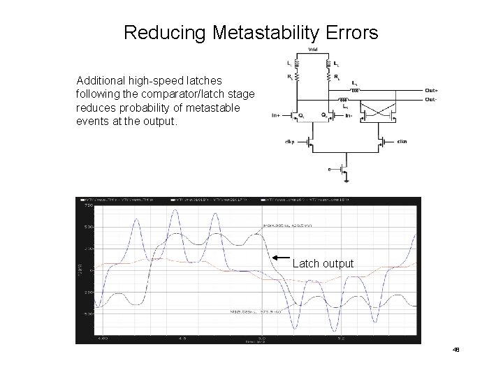
Reducing Metastability Errors Additional high-speed latches following the comparator/latch stage reduces probability of metastable events at the output. Latch output 48
- Slides: 49