Environmentfriendly clean energy Natural gas fired cogeneration Current


- Slides: 34

Environment-friendly clean energy Natural gas fired cogeneration Current status and future overview in Japan Yasutaka Kume The Japan Gas Association 1

Contents 1. Outline of natural gas fired cogeneration 2. Positioning in the context of energy and environmental policies 3. Diffusion 4. Cases of application 5. Technology development 2

(1)Characteristics of cogeneration ① Supply both heat and electricity ② Distributed power source ③ Deal with various demands such as; communities, factories, offices, homes 3

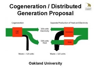
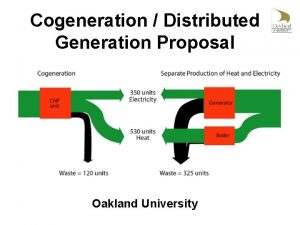
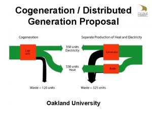
(2)Profile of natural gas cogeneration Case of conventional power generation systems (thermal power) Case of cogeneration systems Gas production plant Electrical power plant Gas fired cogeneration Site of demand Pip el Electricity ine Primary energy Elec trici ty Heat Primary energy (natural gas) (Petroleum, natural gas, coal, etc. ) Electrical energy Transmission loss, etc. Waste heat capable of effective use Energy use Unused waste heat (discarding in the ocean, etc. ) Energy use Waste heat incapable of effective use 4

(3)Advantages of natural gas cogeneration Energy-saving, environmentpreserving characteristics Leveling of electrical power load Natural gas cogeneration system Distributed Energy system Reliable supply of energy Economical efficiency 5

(4)Energy-saving and environment-preserving characteristics Gas fired cogeneration system Conventional system CO 2 emission level: 178 g-C CO 2 emission level: 185 g-C Primary energy: 3, 172 kcal Generating efficiency 30% City gas 0. 29 m 3 Electrical power: 1 k. Wh Demand-end generating efficiency 38% Thermal power generation CO 2 emission level: 103 g-C Primary energy: 2, 450 kcal Coal Petroleum LNG Primary energy: 1, 762 kcal Cogeneration Heat : 1. 4 Mcal Waste heat recovery rate 50% Primary energy consumption: 3, 172 kcal (▲ 25%) CO 2 emission level: 185 g-C (▲ 34%) Efficiency 90% City gas Boiler 0. 16 m 3 Primary energy consumption: 4, 212 kcal CO 2 emission level: 281 g-C Figures for efficiency are based on the lower calorific value standard. Notes: 1) The efficiency figure for gas fired cogeneration is based on an example (calculated using data from the 1997 edition of the “Quality of the Environment in Japan”). 2) Prime units of CO 2 emission: - City gas: 642 g-C/Nm 3 - Electrical power: 178 g-C/k. Wh (based on thermal power standards and at the demand end; calculated using data from the Federation of Electric Power Companies of Japan) 6

(5)Types of cogeneration Gas engine power generation system System Characteristics Single-effect absorption chiller Chilled water Warm water City gas Electricity Gas engine Fuel cell power generation system (phosphoric acid fuel cell) Gas turbine power generation system Double-effect absorption chiller Waste heat boiler Chilled water Steam Electricity City gas Generating efficiency: 30 - 38% (based on the lower calorific value) Rate of waste heat capable of use: 45 - 50% Waste heat: warm water (with a portion capable of recovery by steam) Single-system capacity: generally in the range of 15 - 3, 000 k. W Application fields: hotels, hospitals, athletic facilities, multiuse buildings, large commercial buildings, large office buildings, etc. Generating efficiency: 24 - 33% (based on the lower calorific value) Rate of waste heat capable of use: 50 - 60% Waste heat: steam Single-system capacity: generally in the range of 1, 000 - 10, 000 k. W Application fields: district heating and cooling plants, large buildings, industries Gas turbine Warm water Steam Chilled water Double-effect absorption chiller City gas Fuel cell Electricity Generating efficiency: 40 - 42% (based on the low calorific value) Rate of waste heat capable of use: 30 - 40% Waste heat: warm water, steam Single-system capacity: generally in the range of 100 - 1, 000 k. W Application fields: hotels, hospitals, athletic facilities, multiuse buildings, large commercial buildings, large office buildings (in operation around the clock) 7

2.Positioning of natural gas fired cogeneration in the context of energy and environmental policy Gas fired cogeneration to be encourage for further diffusion as demand-side “new energy” by the government and industries Goal for fy 2010 4, 640, 000 k. W 8

New energy targets (as of July 2001) FY 2001(actual) Photovoltaic : 452, 000 k. W, Wind : 312, 000 k. W FY 2002(actual) Natural gas fired Co-Gen : 2, 150, 000 k. W 9

Measures to promote the diffusion of cogeneration systems in Japan 1. Subsidized projects (1) Support for new energy companies(New energy) (2) Projects to promote the input of new district energy(New energy) (3) Projects for support of companies rationalizing energy utilization (Energy saving) 2. Tax incentives, and fiscal investment and loans (1) Tax measures to promote investment for restructuring of the energy supply and demand (2) Low-interest financing for installation of cogeneration systems, fuel cells, etc. 10

3.Diffusion 11

Diffusion of natural gas fired cogeneration in Japan Total (installed capacity) (Thousands of k. W) Industrial segment (single-FY) Non-industrial segment Cumulative installed capacity 2、149、000kW Except ST Cumulative installed capacity Single-FY installed capacity (Thousands of k. W) Fiscal year 12

Breakdown of installed capacity in the industrial segment by field (total: 2. 03 million k. W) Metals 2. 1% Other fields 6. 6% Ceramics Printing 1. 3% 5. 1% Textiles 1. 0% Electric machine 5. 1% Chemicals 27. 0% Food products 10. 3% Machinery 13. 4% Steel 16. 6% Pulp 15. 1% 13

Breakdown of installed capacity in non-industrial segment by field (total: 650, 000 k. W) Sports facilities 3. 1% Schools 3. 1% Leisure facilities 2. 7% Welfare facilities 1. 2% Housing 0. 2% Restaurants 0. 2% Other fields 3. 3% Combined-use facilities 4. 1% District cooling centers 30. 8% Training/research facilities 4. 2% Lodging facilities 4. 3% Offices 12. 4% Hospitals Facilities for sales of goods 14. 9% 15. 5% 14

A theme in the cogeneration promotion CO 2 emission factors for commercial electricities 15

CO 2 emissions factors for commercial electricities l There are mainly two ways of thinking for CO 2 emissions factors. Average emissions factors : AEF CO 2 emission amount in thermal power plants all generating output in nuclear/hydraulic/thermal plants = (CO 2 emission from nuclear and hydraulic plants ≒ 0) ) Thermal standard (marginal) emissions factors → MEF = l. AEF CO 2 emission amount in thermal power plants generating output in thermal plants is half as much as MEF (Demand end conversion) only fuel parts(not LCCO 2) From the Midterm Summary by the Target Achievement Scenario Sub-Committee in the Central Environment Council Global Environment Committee *Japanese power source breakdown thermal: 55%, nuclear: 35%, hydraulic: 10% 16

What is the alternative power sources? Thermal annual generating output responds to annual demand decrease T T H Total annual power generating output N (no measure case) N H the change in annual electricity demand. l原Nuclear plants are operated to their maximums since their running costs are low. l. TThe operating rate is 99. 4% except for the periodic inspection times. l. NNuclear and hydraulic are operated by the priority dispatching directive l水 Hydraulic plants are operated to their maximums since their running costs are low. l. RThe generating output depends on rainfall/snowfall levels. l需 (measures adopted case) Thermal power generation is the marginal power source in the present Japanese condition 17

How thermal standard MEF socially recognized? ★“Guideline for calculation of Greenhouse gases(GHGs) total emission amount" based on the law Guideline of Measures to Prevent Global Warming (Environment Agency in July 1999) AEF is to be used for the calculation of GHGs total emission amount. It is stated that "evaluation of the effect in each measure associated with electricity use are to be investigated in the future". ★The Midterm Summary by the Target Achievement Scenario Sub-Committee in the Central Environment Council Global Environment Committee(in July 2001) The effect of each measure is to be calculated using both AEF and MEF ★Guideline of Measures to Prevent Global Warming(in March 2002) The effect of each measure is to be calculated using both AEF and MEF, and present as in the range of ○○~△△. 18

Evaluation of CO 2 reduction effect in cogeneration system Gas fired cogeneration system Conventional system CO 2 emission level : 178 g-C (MEF ) 97 g-C (AEF ) Primary energy: 2,450 kcal CO 2 emission level : 222 g-C Electrical power: 1 k. Wh Primary energy: 3,807 kcal Generating efficiency 25% Demand-end generating efficiency 38% City gas 0.35 m 3 Coal Petroleum LNG Thermal power generation nuclear/hydraulic CO 2 emission level : 99 g-C Primary energy: 1,692 kcal Cogeneration Heat : 1. 4 Mcal generation efficiency is based on LHV Waste heat recovery rate 40% Primary energy consumption : 3, 807 kcal (▲ 8%) CO 2 emission level : 222 g-C (▲ 20% : MEF) (+ 12% : AEF) Efficiency 90% City gas Boiler 0.15 m 3 Primary energy consumption : 4, 142 kcal CO 2 emission level : 277 g-C (MEF) 196 g-C (AEF) CO 2 emission coefficient: city gas 642 g-c/Nm 3, electricity 178 g-c/k. Wh(MEF), 97 g-c/k. Wh(AEF); demand-end Source : Actual values in 1995 from data by the Federation of Electric Power Companies of Japan 19

4.Case of application 20

Overview of Roppongi Hills Energy Supply Project (1)Supply electricity depending on the demand of specific supply site. Electricity Industry Law amended in 1995 (2)Roppongi 6 th square(6 -chome) redevelopment project Cultural city center where people live, work, relax, and create in a safe atmosphere. (3)Final completion in 2003 spring (4)Area: 12. 7 ha Total floor space: 750, 000 m 2 21

Building Image Office building A Residential building B Residential building C Residential building A Office building B Roppongi Hills Gate Tower Hotel building Residential building D Theater building Complex building station plaza Broadcasting Center 22

Outline of energy supply facilities Electricity supply facilities 36, 500 k. W Steam injected gas turbine 36, 000 k. W (6, 000 k. W × 6) Back pressure steam turbine 500 k. W Heat supply facilities Cooling source Steam absorption refrigerating system Heating source Steam boiler 66, 810 k. W (19, 000 RT) 179, 600 MJ/h (79. 6 t/h) 23

Electricity/Heat Supply Planned area Roppongi 6 th square section District cooling/heating facilities & Electricity supply facilities Building for electricity/heat supply Building for heat supply Heat supply pipe Electricity supply line 24

5.Technology development 25

Classification of energy demand fields, and demand cultivation New technology for demand cultivation Share of the energy demand occupied by electrical power Polymer Electrolyte Fuel Cells (PEFC) Micro gas turbines High-efficiency gas engines and gas turbines Fields as yet uncultivated Convenience stores Offices and stores Residential Fast food restaurants Small-scale, commercialuse Factories(metals/ machinery) Factories (paper/ food products) Hospitals and hotels District heating and cooling systems Large-scale commercialuse Fields now being cultivated Industrialuse Cogeneration system generation capacity 26

Micro cogeneration - current status and development situation Electrical efficienc y Fuel cell (PEFC) Efficiency of a 1 -k. W system: 35% 40 (micro turbine) Allied. Elliot Signal 社gas (マイクロGT) Yanmar (engine) Efficiency of a 9. 8 -k. W system: 24% Efficiency of a 30 -k. W system: 30% 容量75kW 効率 30% 30 Capston (micro gas turbine) Efficiency of a 28 -k. W system: 26% 20 10 Honda Motor (engine) Efficiency of a 1 -k. W system: 20% 10 50 Capacity (k. W) 1 00 27

Conception of (PEFC) fuel cells for residential use 1 -k. W hydrogen-fueled system proposed by Sanyo Electric (from the company website) Separator Hydrogen line Fuel cell Catalytic electrode Solid polymer membrane Air line Blower Hydrogen former Heat exchanger Power exchanger PEFC cell stack Cut-away view of a 250 -W butanefueled system proposed by Matsushita Electric Works (from the company website) Steam generator Hydrogen reforming catalyst Electric power CO removal catalyst Air feed blower Cassette cylinder Water tank Pump 28

Conception of a residential-use fuel cell cogeneration system Electricity Fuel cell system Air conditioner Lighting Inverter PEFC cell City gas Reformer Hot water tank Storage cell Bath Supplementary heating Hot water supply Underfloor heating system 29

Commercial-use micro gas engine 9. 8 k. W Generated output Single-phase: 100/200 V Waste heat recovery 24. 2 k. W 21. 9 k. W Power generation 23. 5% 25. 5% Heat recovery 58% 57% Efficiency Generation voltage Three-phase: 200 V Outside dimensions 1, 460(W)× 730(D)× 1, 610(H) Noise level 60 d. B(A) 30

System composition (example) System example Gas engine Multi switcher Water heating system Water heater Synchronization CPU Commercial power Detection Generated power Hot water tank Control power source Load Gas Hot water mixer Hot water Water supply Load 31

Micro gas turbines are a new type of compact, dispersed power generation system based on proven technologies, including auxiliary power equipment with a record of military and aircraft use, constituent technology applied in heat exchangers for large gas turbines, and mass production technology applied in automotive turbochargers. As such, in recent years, they have become a focus of attention in the power and gas industries overseas, and more than ten firms, consisting of both major manufacturers and venture businesses from inside and outside Japan, are vying with each other in their development. In Western markets, leading overseas manufacturers have already commenced shipments of initial lot products, and are steadily constructing production facilities with a view to getting orders for several tens of thousands of systems before the first half of the decade is over. In Japan, systems began to be installed in restaurant chains in fiscal 2000, and extensive installation in the market as a whole is anticipated to begin in fiscal 2001. Regenerator Exhaust gas Waste heat recovery unit City gas Generated output Combustor Inverter (frequency controller) Air bearing Intake air High-speed generator Combustion air compressor Turbine 32

Future outlook for the cogeneration market • Power wholesalers and retailers (independent power producers, etc. ) • Waste power generation projects • Community re-development, heat supply projects, district heating/cooling system • Private power generation in the industrial and commercial segments (expansion into application areas with a smaller heat-power ratio) • Private power generation at small and medium enterprises • Private power generation for residential use 33

Thanks for your kind attention! Yasutaka Kume Energy System Department The Japan Gas Association Tel: +81 3 3502 2468 E-mail: kume@gas. or. jp 34
 Clean up everybody let's clean up
 A balanced delta connected load having an impedance 20-j15
 Line current and phase current
 N=nc exp(-eg/2kt)
 Lesson 4 three-phase motors
 Drift current and diffusion current in semiconductor
 Ceramic composition resistors
 Pinch off voltage
 Balanced delta delta connection
 Infineon
 Drift current and diffusion current in semiconductor
 Which electrode is positive
 Hazard based safety engineering
 Mesh current method with current source
 Fired heater performance
 Nobody got fired for buying ibm
 When the pellet fired into the spiral tube
 When the pellet fired into the spiral tube
 What are the 3 newton's laws
 We took a little trip down the mighty mississippi
 A machine fired several projectiles
 Second law of motion examples
 What did caesar do that insulted the senators
 Equivalent evaporation of boiler formula
 Vertical motion formula
 A ten inch fireworks shell is fired
 Diesel fired steam boiler
 A rocket initially at rest is fired vertically
 Movianto spain
 The first shots are fired achieve 3000 answers
 Clean energy smart manufacturing innovation institute
 Define renewable energy source
 Clean energy regulator australia
 Umass clean energy extension
 Retscreen

