Environmental EngineeringI Prof Rajesh Bhagat Asst Professor CED

Environmental Engineering-I Prof. Rajesh Bhagat Asst. Professor, CED, YCCE, Nagpur B. E. (Civil Engg. ) GCOE, Amravati M. Tech. (Enviro. Engg. ) VNIT, Nagpur Experience & Achievement: Selected Scientist, NEERI-CSIR, Govt. of India. GATE Qualified Three Times. Selected Junior Engineer, ZP Washim. Three Times Selected as UGC Approved Assistant Professor, PCE, Nagpur. Assistant Professor, Cummins College of Engg. For Women (MKSSS, Nagpur) Topper of Pre-Ph. D Course Work at UGC-HRDC, RTMNU Nagpur Mobile No. : - 8483002277 / 8483003474 Email ID : - rajeysh 7 bhagat@gmail. com Website: - www. rajeysh 7 bhagat. wordpress. com
 Introduction: Importance and necessity of water supply scheme. 2) Water Demand: Types")
UNIT-I 1) Introduction: Importance and necessity of water supply scheme. 2) Water Demand: Types of demand, factors affecting per capita demand, variation in demand, design period and population forecasting methods and examples. 3) Sources of Water: Ground water – springs, infiltration galleries, Dug wells, tube wells, Surface water – stream, Lake, River, impounding reservoirs, ponds, etc. 4) Intake Structures: Location types – river, lake, canal, reservoir, etc. 2
 Conveyance of Water: Types of pipe, joints , valves &")
UNIT - II 1) Conveyance of Water: Types of pipe, joints , valves & fittings. 2) Hydraulic Design Aspects: Manning’s, Darcy’s Weisbach, Hazen Williams Formulae & Numerical. 3) Rising Main & Pumps: Types, working merits and demerits selection of pumps. 3
 Water Quality : General idea of water borne diseases, Physical,")
UNIT – III 1) Water Quality : General idea of water borne diseases, Physical, Chemical and biological characteristics of water, Standards of drinking water. 2) Water Treatment : Objective of treatment, unit operations and processes. 3) Treatment Flow sheet of conventional water treatment plant. 4) Aeration: Purpose, types of aerators. 5) Coagulation & Flocculation: Definition, Principals, types of coagulants and Reactions, coagulant doses, types of mixing and flocculation devices. 4
 Water Supply & Sanitary Engineering by G. S. Birdie & J. S.")
References: 1) Water Supply & Sanitary Engineering by G. S. Birdie & J. S. Birdie, Dhanpat Rai Publication, New Delhi. 2) Water Supply Engineering (Vol. – I) by B. C. Punmia, Laxmi Publication, Delhi. 3) Water Supply Engineering (Vol. – I) by S. K. Garg, Khanna Publishers, Delhi. 4) Solid Waste Management by A. D. Bhide & Sunderson. 5) Water Supply Engineering (Vol. – I) by Modi P. N. , Standard Book House Rajsons Publication, New Delhi.
 List out the various joints used in Water Supply Scheme")
UNIT-II QUESTIONS BANK 1) List out the various joints used in Water Supply Scheme and explain anyone. 2) With neat sketches explain the various types of pipe Joints used in CI pipes. 3) List out the types of pipes or conduits used in WSS and discuss their advantages. 4) Why is pumping of water required in WSS? What factors affect the selection of pump? 5) Describe the various types of pumps used in water supply with its advantage and disadvantage. 6) Explain the various formulae used to determine the loss of head in pipes. 7) Calculate the BHP of a pump, if total quantity of discharge is 900 lit/sec and total head against which pump has to work is 60 m, assume suitable efficiency of pump. 8) Water is to be supplied to a town of population 2. 5 lakhs. If the water work is situated at an elevation of 50 m lower than the source, calculate the size of gravity mains of 25 km length. If the water demand 270 lpcd. 9) Determine hydraulic gradient for a pipe of diameter 1. 5 m carrying water at a rate of 2. 4 m 3/s. (Use: - f = 0. 003, m = 0. 011, CH = 135) 10) Write a short note on: a) Sluice Valve, b) Checked Valve, e) Air Relief Valve, f) Scour Valve, i) Socket Joint, j) Spigot Joint & c) Gate Valve, d) Pressure Relief Valve, g) Centrifugal Pump, h) Pipe Materials in Water Supply J) Reciprocating Pump. 6

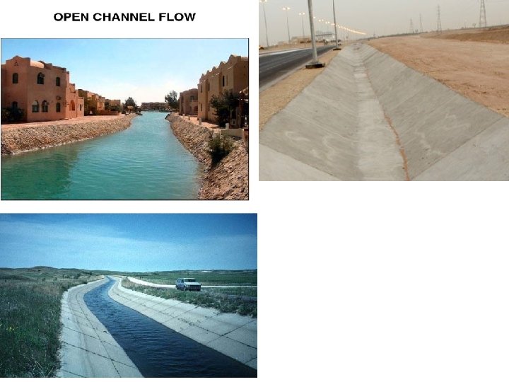
Conveyance of Water Source Intake Distr. System WTP CONDIUT: - Any structure for transportation of water from source to WTP & subsequent distribution to city. Conduit Gravity Open Channels Aqueducts Pressure Tunnels Flumes Pipe Tunnels

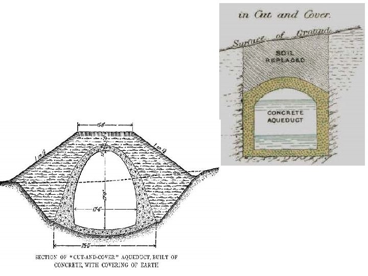
Open Channels: Ø Easily & cheaply constructed by cutting the grounds Ø Channels should be lined properly to prevent seepage Ø Velocity should not exceeds 0. 9 m/s Aqueducts: Ø Closed conduit constructed with masonry or concrete Ø Old days rectangular aqueducts were used but now days horse shoe or circular section are used Ø Avg. velocity = 1. 0 m/s

Tunnels: Ø Gravity conduits but sometimes water flows under pressure Ø Mostly constructed in horse shoe c/s but pressure tunnels have circular c/s Flumes: Ø Open channels supported over the ground by trestles Ø Used for conveying water across valleys & minor low lying areas or over drains & other obstruction coming in the way Ø Constructed with RCC, wood, metal, etc. Ø Common section are rectangular or circular

Tunnels:

Flumes:

Pipes: Ø Circular conduits in which water flows under pressure or gravity Ø Now days pressure pipes have eliminated the use of channels, aqueduct, tunnels, etc. Ø Made up of various material 1) Cast Iron 2) Wrought Iron 3) Steel (MS) 4) Cement Concrete 5) Asbestos Cement 6) Timber 7) Plastic 8) Copper 9) Lead 10) Vitrified Clay
 Carrying capacity of pipe (Coefficient of roughness)")
Factors Affecting Selection of Pipe Material: 1) Carrying capacity of pipe (Coefficient of roughness) 2) Durability and life of pipe 3) Type of fluid or water to be conveyed & its corrosive effects 4) Internal and external corrosion problems 5) Type of soil 6) Strength of the pipe & measured by its ability to resist internal pressure and external loads 7) Availability of funds 8) O & M cost 9) Safety, economy, & availability of pipe 10) Maximum permissible diameter 11) Ease or Difficulty of transportation , handling and laying and jointing under different conditions 12) Skilled labor
 2) 3) 4) 5) Long life about 100 years High")
Cast Iron Pipes: 1) 2) 3) 4) 5) Long life about 100 years High corrosion resistant ability Used when pipe diameter is less than 90 cm Length of pipe is 3 to 6 m Bell & spigot joints are for CI pipes in distribution system while flanged joints are for rising main 6) Economical, strong, durable & long life 7) 8) 9) 10) 11) 12) 13) 14) 15) Corrosion resistant Easy to join with each other Impact resistance Cant be used if pressure greater than 7 kg/cm 3 Uneconomical when dia. More than 120 cm Erosion of pipe from inside Roughness from inside causes reduction of flow Very heavy and difficult to transport Brittle and fragile

Cast Iron Pipes: 12/21/15
 2) 3) 4) 5) 6) 7) 8) 9) 10) 11) 12)")
Steel Pipes: 1) 2) 3) 4) 5) 6) 7) 8) 9) 10) 11) 12) 13) 14) Used for mainlines & where pressure are high & dia. is more Jointed by welding or riveting or flexible joints or other filler joints Available in small or large diameter Prevented from internal corrosion through coal tar / asphalt lining High Tensile strength Very light weight & withstand high pressure Less thickness as compared to CI pipe Best suited for high dynamic loading Laying & joining easy Life is 25 to 30 years Cant withstand external loads Affected by corrosion & costly to maintain Flow carrying capacity gets reduced due to riveting Cant used in distribution system

Steel Pipes:
 2) Used when water flows under gravity 3) 4) 5) 6)")
Concrete Pipes: 1) 2) Used when water flows under gravity 3) 4) 5) 6) 7) 8) 9) 10) 11) 12) 13) 14) Normally 1: 2: 2 concrete mix is used in manufacturing Plain concrete pipes used when dia. Upto 60 cm & Above 60 cm dia. RCC pipes are used Bell & spigot , collar joint and flush joints are used Corrosion resistant Smooth from inside hence reduces frictional losses Long life = 75 years Carrying capacity doesn’t reduces with time Low maintenance cost Suitable to resist external loads Heavy & difficult to handled May get cracked during transportation Repairing is difficult Cant withstand high pressure

Concrete Pipes: 12/21/15
 2) 3) 4) 5) 6) 7) 8) 9) 10) 11)")
Asbestos Cement Pipes: 1) 2) 3) 4) 5) 6) 7) 8) 9) 10) 11) 12) Mixture of Portland cement and asbestos fibers Manufactured from 5 to 130 cm in dia. Withstand high pressure from 3. 5 to 25 kg/cm 2 Not affected by salt, acids & other corrosive materials & remains smooth Very light therefore easy to transport & handle Easily cut, fitted, drilled trapped and jointed Offer less friction therefore good carrying capacity Costly Fragile and brittle Very weak in sustaining impact Not durable Cant be laid in exposed places

Asbestos Cement Pipes: - 12/21/15
 Now days plastic pipes are extensively used 2) Corrosion resistance, light")
Plastic Pipes: 1) Now days plastic pipes are extensively used 2) Corrosion resistance, light weight, economical 3) PVC pipes most commonly used among plastic pipes in India 4) Internal plumbing and rural supply scheme 5) High smooth flow with reduced friction losses 6) Withstand to high moist & corrosive environment 7) Immune to chemicals 8) Do not provide any favorable condition to bacteria 9) Joining, bending & installation is easy 10) Not strong like CI pipe 11) Thermal expansion coefficient is high 12) Plastic imparts taste to water
 Manufactured by rolling the flat plates of the metal to")
Wrought Iron Pipes: 1) Manufactured by rolling the flat plates of the metal to the proper diameter & welding the edges 2) 3) Coated or galvanized with zinc to increase the life Should be used in building to protect from corrosion Cement lined Cast Iron Pipes: 1) 2) Cast iron pipes are lined with cement to protect them against corrosion Have very small coefficient of friction Vitrified Clay Pipes: 1) 2) 3) Extensively used for carrying sewage and drain water Provide smooth surface and free from corrosion Length of pipe = 60 to 120 cm

Vitrified Clay Pipes:
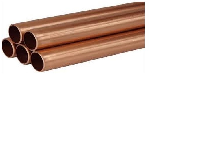
 2) 3) 4) 5) Copper pipes are not liable")
Copper and Lead Pipes: 1) 2) 3) 4) 5) Copper pipes are not liable to corrosion Used in house connection and carrying hot water Can withstand high internal pressure Lead pipes are not used in India bcoz causes lead poisoning Used in sanitary fitting & chlorination & alum dosing Wooden Pipes: 1) 2) 3) 4) 5) Light weight, Easy to laid Easily repaired, Cheap, Life = 30 to 35 years Corrosion resistance, Low coefficient of friction Leak under varying pressure hence, not suitable for intermittent supply system Collapse under heavy external load

Pipe Joints: Ø Pipe are manufactured in small length of 2 to 6 m for the facilities in handling, transportation and placing in position. Ø These small pieces of pipes are then joined together after placing in position, to make one continuous length of pipe line. Types of Joints: - 1) Bell & Spigot Joint 2) Flanged Joined 3) Mechanical Joined 4) Flexible Joint 5) Expansion Joint 6) Screwed Joint 7) Collar Joint 8) A. C. Pipe Joint
 Socket and Spigot joint. 2) Commonly used for CI")
Bell and spigot joint 1) Socket and Spigot joint. 2) Commonly used for CI pipes. 3) One end is enlarged is called socket or bell while other is normal end (spigot). 4) Spigot inserted into socket & empty space is filled by molten lead 5) Joint is flexible but requires skilled labor 6) May be used for RCC pipes 7) For economy sometimes cement mortar are also used in place of lead 8) Hemp yarn fiber uses to maintain the alignment
 Mostly used for temporary pipe lines (CI, Concrete pipes, etc. )")
flanged joint 1) Mostly used for temporary pipe lines (CI, Concrete pipes, etc. ) 2) Flanges at both ends 3) Pipes two ends are brought in perfect level to join each other. 4) Before flanges bolted rubber gasket are placed. 5) Cant be used where vibration and deflection of pipes, etc.
 Two plain ends are joined together by means of mechanical coupling.")
mechanical joint 1) Two plain ends are joined together by means of mechanical coupling. 2) Used in CI, Wrought Iron & Steel pipes. 3) Mechanical Victaulic joint consist of a U shaped rubber ring enclosed by a metal housing made in two parts. 4) These two parts are then bolted together to form a ring around the pipe. 5) Mechanical Dresser Coupling joint consists of an iron ring & gasket which are slipped over each abutting ends of the pipes and an iron sleeve is inserted. 6) The iron rings are then tighten by nuts & bolts.

flexible joint Ø Where settlement is likely to occur after the laying of the pipes specially on curves. Ø Pipes can be laid at angle Ø If one pipe is given any deflection the ball shaped portion will move inside the socket and the joint will remain waterproof in all the positions.

expansion joint Ø CI, Concrete Pipes Ø Where pipes expand or contract due to change in temperature Ø Thus checks thermal stresses in the pipes.

screwed joint Ø Connecting small diameter CI, WI, & galvanized pipes. Ø Ends of pipes have threads on outside, while coupling or socket has threads on the inner side. Ø Zinc paint or hemp yarn should be placed in the threads of the pipe to make water tight joint.

collar joint Ø Mostly uses for joining big diameter concrete & asbestos cement pipes. Ø Two ends of pipes are brought in one level Ø 1: 1 cement mortar is filled in the space between pipe & collar as shown.

Simplex joint Ø Small diameter Asbestos cement pipe Ø Two ends of pipes are kept against each other & then two rubber ring will be slipped over the pipes. Ø The coupling will be pushed over the rubber rings as shown in figure. Rubber rings make the joint water proof.
 Water pipes can be laid at any depth, below the")
Hydraulic Design Aspects 1) Water pipes can be laid at any depth, below the hydraulic gradient line, the velocity in the pipes depends on the pressure head at the point. 2) The hydraulic gradient line should neither too high nor too low. It should be near to pipe line. 3) If the velocity is kept low, large diameter pipe will be required to carry the required quantity of water. 4) If the velocity is kept high, cost of pumping, pipe & its fitting will increase. 5) Self cleansing velocity ie no silting or normal velocity- 0. 6 to 3 m/s (0. 9 to 1. 5 m/s) 0. 9 m/s
 This formula usually used in determining the loss of head in")
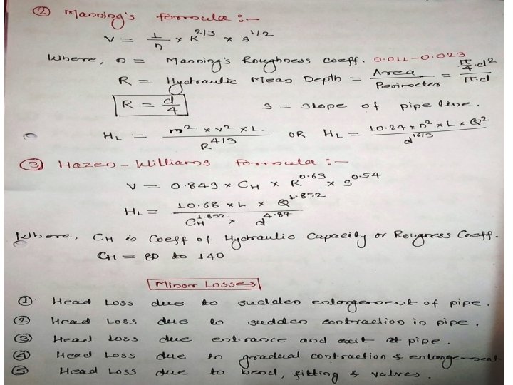
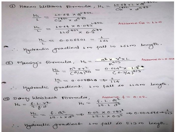
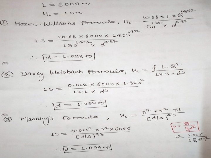
Manning’s Formula 1) This formula usually used in determining the loss of head in the gravity conduits. 2) This formula equally applicable to the turbulent flow in pressure pipes. HL = (m 2 x V 2 x L) / (R 4 / 3) HL = Head Loss in m. m = Manning’s Constant or roughness coefficient = 0. 011 L = Length of pipe line in meter. V = velocity of flow in m/s R = Hydraulic mean depth = (Area / Perimeter) = (d/4) d = Diameter of pipe in meter.
 This formula is widely used now days in designing the")
Hazen Williams Formula 1) This formula is widely used now days in designing the pipe lines. 2) The value of CH is more for smoother pipe and less for rough pipe. V = 0. 85 x CH x R 0. 63 x S 0. 54 HL = (10. 68 x L x Q 1. 852 ) / ( CH 1. 852 x D 4. 87 ) CH = Coeff. Of Hydraulic Capacity = 135 L = Length of pipe line in meter. V = velocity of flow in m/s R = Hydraulic mean depth = (Area / Perimeter) = (d/4) S = slope of energy line or pipe.
 / (2 x")
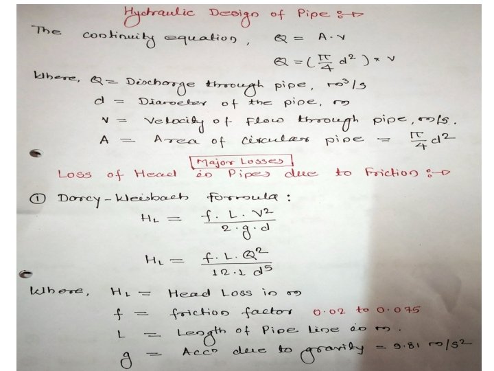
Dracys Weisbach Formula HL = (f x L x V 2) / (2 x g x d) g = Acceleration due to gravity in m/s 2 = 9. 81 m/s 2 F = friction factor = 0. 02 to 0. 075. L = Length of pipe in m. d = Diameter of pipe in m. Q = Discharge through pipe in m 3/s V = Velocity through Pipe in m/s = Q /A

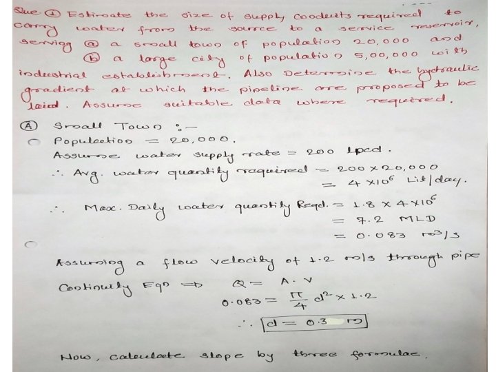
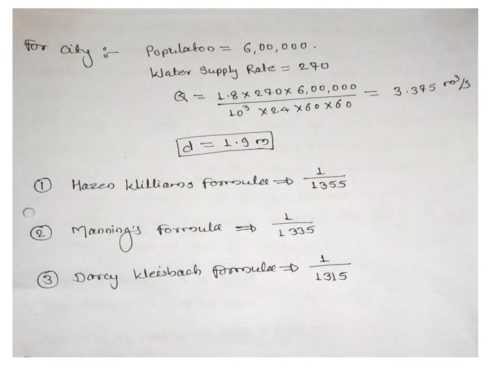
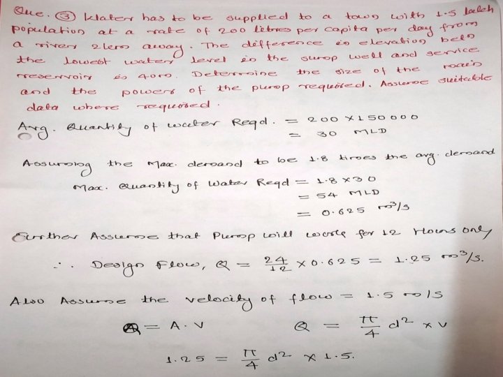
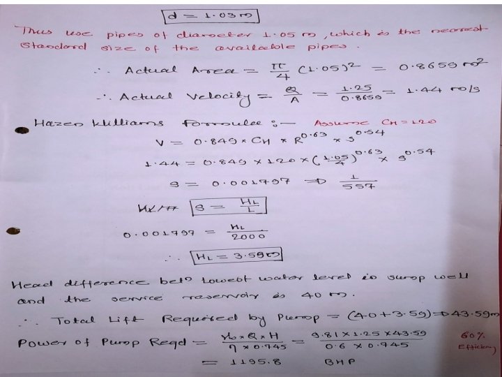
Que. 1. Water has to be supplied to a town with one lakh population at the rate of 150 liter/capita/day from a river 2000 m away. The difference in elevation between the lowest water level in the sump and the reservoir is 40 m. If the demand has to be supplied in 8 hours, determine the size of the main and the brake horse power of the pump required. Assume maximum demand as 1. 5 time the average demand. Assume f = 0. 03, velocity in the pipe = 2. 4 m/s and efficiency of pump = 80%. Sol: Avg. Water Demand = 100000 x 150 = 15 MLD Maximum Water Demand = 1. 5 x 15 = 22. 5 MLD Max. Discharge Required, Q = (22. 5 x 10⁶ ) / (103 x 8 x 60) = 0. 7812 m 3 /s A = ( Q / v) : - ( ∏ / 4 ) x d 2 = ( 0. 7812 / 2. 4 ) d = 0. 644 m HL = (f x L x V 2) / (2 x g x d) HL = (0. 03 x 2000 x 2. 42) / (2 x 9. 81 x 0. 644) = 27. 36 Required lift head between sump and reservoir = 40 m Total Head Against which pump has to work = 40 + 27. 36 = 67. 36 m Brake Horse Power = (γw x Q x H ) / (η x 0. 7457) = (9. 81 x 0. 7812 x 67. 36 ) / (0. 8 x 0. 7457) =865. 3 BHP (645. 2 K Watt)

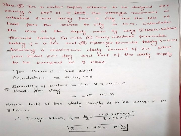
Que. 2. For a town with a population of 2 lakhs, a water supply scheme is to be designed. The maximum daily demand may be assumed as 200 liters/capita/day. The storage reservoir is situated 5 km away from the town. Assuming loss of head from source to town as 10 m and friction factor for the pipe material as 0. 048, recommend the size of supply main. 50% of daily demand has to be pumped in 8 hours for the proposed scheme. Sol: Maximum Daily Water Demand = 200 LPCD Maximum Water Demand = 200000 x 200 = 40 MLD Maximum Water Demand for which supply main is to be designed = 50% of daily demand Q = (50 / 100) x 40 x 106 Liters per 8 hours Q = (50 / 100) x (40 x 106) / (8 x 60) Q = 0. 694 m 3 /s L = 5000 m HL = 10 m f = 0. 048 HL = (f x L x v 2) / (2 x g x d) 10 = (0. 048 x 5000 x v 2) / (2 x 9. 81 x d) v = ( Q / (∏ /4)) x d 2 v = ( 0. 694 / (3. 14 /4)) x d 2 10 = (0. 048 x 5000 x (0. 884 d 2)2) / (2 x 9. 81 x d) d = 0. 99 m v = 0. 884 / d 2

Pumps Ø The hydraulic machines which convert the mechanical energy into hydraulic energy is called as pumps. Ø The device or machine which is used to lift the water from lower elevation to higher elevation.

Classification of Pumps I. Based on Principle of operation: 1. Displacement pump 1. Reciprocating pump 2. Rotary pump 2. Centrifugal pump 3. Airlift pump 4. Impulse pump II. Based on the type of power required: 1. Electrically Driven Pump 2. Gasoline Engine pump 3. Steam Engine pump III. Based on the type of service: 1. Low lift pump 2. High Lift Pump 3. Deep Well pump 4. Booster pump 5. Stand by pump
 To lift the raw water from the source of supply,")
NECESSITY OF PUMPING 1) To lift the raw water from the source of supply, such as lake, reservoir, river or well, etc 2) At WTP, to lift the water for various operation such as back washing of filters, pumping of chemicals, dewatering of tanks, etc 3) To lift the treated water to overhead tanks or elevated distribution reservoir. 4) To deliver treated water to the consumer’s taps at reasonable pressure. 5) To increase the discharge or velocity by boosting up the pressure in water distribution network. 6) To supply water under pressure for fire hydrants.
 Capacity of the pump. 2) Number of pump units required.")
SELECTION OF PUMPS 1) Capacity of the pump. 2) Number of pump units required. 3) Suction conditions. 4) Lift (total head). 5) Discharge condition &variations in the load. 6) Floor space requirement. 7) Flexibility of operation. 8) Starting and priming characteristics. 9) Type of drive required. 10) Initial cost and running costs. 11) Labor requirements. 12) Quantity and quality of water to be pumped. 13) Life.
 The displacement pumps are those in which liquid is sucked by")
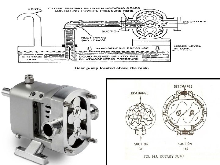
DISPLACEMENT PUMPS 1) The displacement pumps are those in which liquid is sucked by mechanically inducing vacuum in a chamber. 2) It actually displaced due to the thrust exerted on it by a moving member. 3) Lifting the liquid (water) to the desired height. 4) The pump consist of one or more chambers which alternatively filled and emptied with the liquid. TWO TYPES : - 1) Reciprocating pump 2) Rotary pump
 The mechanical energy is converted into hydraulic energy by sucking the")
RECIPROCAING PUMP 1) The mechanical energy is converted into hydraulic energy by sucking the liquid into cylinder in which exerts the thrust on the liquid and increases its hydraulic energy, the pump is called as reciprocating pump. 2) Suitable for lifting relatively clean water. 3) Against high and fluctuating head. PARTS: - A cylinder, Suction pipe, Delivery pipe, Suction valve & Delivery valve WORKING: - 1) Consist of a piston which move to and fro in a close fitting cylinder 2) Connected to the suction and delivery pipes 3) A non–return valve which admits water in one direction only.
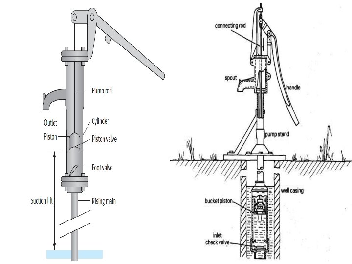

RECIPROCAING PUMP Delivery pipe Cylinder Delivery valve Connecting rod crank PISTON Piston rod Crank rotated at uniform speed by motor VACUUM IS CREATED. Suction take place at on one side of the piston while the other side delivers the liquid Two suction and delivery strokes in one revolution of crank
 Single cylinder pump 2) Double cylinder")
Depending upon the number of cylinder : 1) Single cylinder pump 2) Double cylinder pump 3) Triple cylinder pump 4) Double action pump 5) Quintuplex pump
 Two gears or cam a mesh together and rotate in opposite")
ROTARY PUMP: 1) Two gears or cam a mesh together and rotate in opposite directions 2) Water is drawn up the suction pipes 3) Trapped between the teeth and casing 4) Forced out into the discharge pipe 5) No valve are required 6) Not in common use in water works
 The mechanical energy is converted into pressure energy by means of")
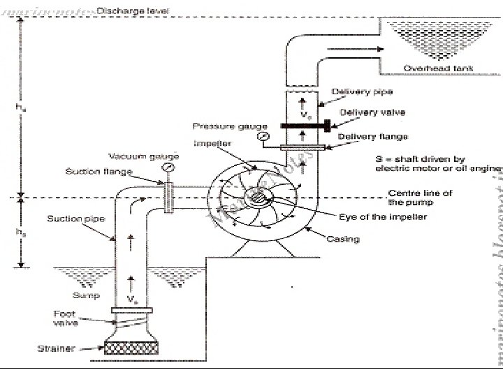
CENTRIFUGAL PUMPS: 1) The mechanical energy is converted into pressure energy by means of centrifugal force acting on the fluid, the hydraulic machine is called is centrifugal pumps 2) Pump under steady low head, through the water may be even turbid 3) Lifting raw water from the river to the treatment plants 4) Lifting treated water to the distributed reservoirs. Ø A certain mass of liquid is made to rotate by an external force. It is thrown away from central axis of rotation and a centrifugal head is impressed which enables it to rise to higher level. MAIN PARTS: - 1) Impeller 2) Casing 3) Suction pipe with a foot valve and a strainer 4) Suction valve 5) Delivery pipe 6) Eye or hub of pump

Types of Centrifugal Pump: -BASED ON CASING: - Ø Volute pump Ø Diffuser NUMBERS OF INPELLER: - Ø Single stage pump Ø Multi-stage pump DIRECTION OF FLOW: - Ø Radial flow pump Ø Axial flow pump Ø Mixed flow pump
 The centrifugal pump employs a rotating impellers with water. 2) Discharged through")
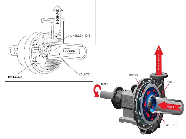
WORKING: 1) The centrifugal pump employs a rotating impellers with water. 2) Discharged through a spiral casing by virtue of the centrifugal force developed due to the rotation of impeller. 3) As the liquid passes through the revolving wheel or impeller. 4) Angular momentum changes, which also results in increasing the pressure of the liquid.
.")
VOLUTE PUMP: Ø The impeller is surrounded by spiral shape casing (volute chamber ). Ø Sectional area of flow around the periphery of the impeller gradually increases from the tongue to the delivery pipe. Ø Volute chamber purpose: -1. Reducing velocity. 2. Increases efficiency of pump.

CENTRIFUGAL PUMP INSTALLATION: -

CENTRIFUGAL PUMP INSTALLATION: Ø Strainer/screen: - Pipe to prevent the entry of debris. Ø Foot valve: -prevent water from leaving the pump (self priming device) Ø Suction pipe / Delivery pipe : - same dia. Ø Accentric reducer: - to prevent air accumulation when the pump is stopped. § Check valve: -To prevent backflow through the pump § Gate valve or discharge valve: -initially kept closed , gradually opened as the pump picks up the speed

COMPARISION OF RACIPROCATIONG & CENTRIFUGAL PUMPS: Characteristics Reciprocating pumps Centrifugal pumps 1. Discharge Øflow Pulsating Øconstant discharge even if head on delivery side varies Ø large amount of losses due to leakage through valves etc ØRun at low speeds ; Piston’s speed less than 30 m/min. Øcontinuous flow Ødoes not give constant discharge under variable head Øno such trouble 2)Speed 3. Efficiency ØRun at high speed(500 to 1000 r. p. m) ØEfficiency between 40 and Long stroke engines have 80%; more efficiency if the 85% efficiency while head and discharge are smaller pumps have only maintained within narrow 40% efficiency limits.

4. Head ØCan work against high ØBetter suited to low heads. 5. Size ØLarge size, bulky and heavy. Requires large space. ØSmall, compact and light. 6. Initial and maintenance ØHigh initial cost; cost maintenance cost is also high. ØLow initial cost. maintenance cost low. 7. Running ØStarting is difficult Ømore power required Øcomplicated mechanism required Øoperation difficult ØStarting is easy Ø less power required Ø simple mechanism ØOperation easier.

MISCELLANEOUS PUMPS: Ø Jet pump Ø Air lift pump
 Jet of water is injected at high velocity into the throat")
JET PUMPS: 1) Jet of water is injected at high velocity into the throat of a venturi tube 2) High velocity stream pulls the water upwards around the tip of the nozzle 3) Create a suction at a the that point 4) Water is carried upward with the high velocity stream 5) Enlarged portion of the venturi , velocity decrease while pressure increase 6) Main advantage : conveniently placed at the ground surface
 A compressor is used to force air into a small")
AIR LIFT PUMPS: 1) A compressor is used to force air into a small diameter pipe (air pipe) 2) Air pipe is placed in bigger diameter discharge pipe (education pipe ) 3) Air is forced into water, air-water mixture is formed whose specific gravity is lower than of water 4) Water rises in education pipe and is discharged out

AIR LIFT PUMPS

Two alternatives to obtain variable discharge at maximum efficiency: - Ø Provision of several pumps of in parallel Ø Provision of several pumps in series

PARALLEL OPERATION OF PUMPS: - Ø Several pumps of smaller capacities in parallel Ø A variable number can be operated at a capacity depending on flow requirements Ø To operate at maximum efficiency Ø Assumed that the head across the each pump is the same

PUMPS OPERATING IN PARALLEL Head is same smaller capacities in llel maximum efficiency

CHARACTERISTIC CURVES FOR IDENTICAL PUMP IN PARALLEL • Assumed that the head across the each pump is the same • Discharged are added

PUMPS OPERARING IN SERIES Ø Same discharge is passes through each pump Ø Adopted in multistage and bore hole Ø Pumps in series operation are to be operated simultaneously. Ø Individual pump manometric head at arbitrary discharges.
")
PUMPS OPERARING IN SERIES: - adding Individual pump manometric head at arbitrary discharges. A) shown the series configuration B) shows the resulting head verses discharge characteristic.

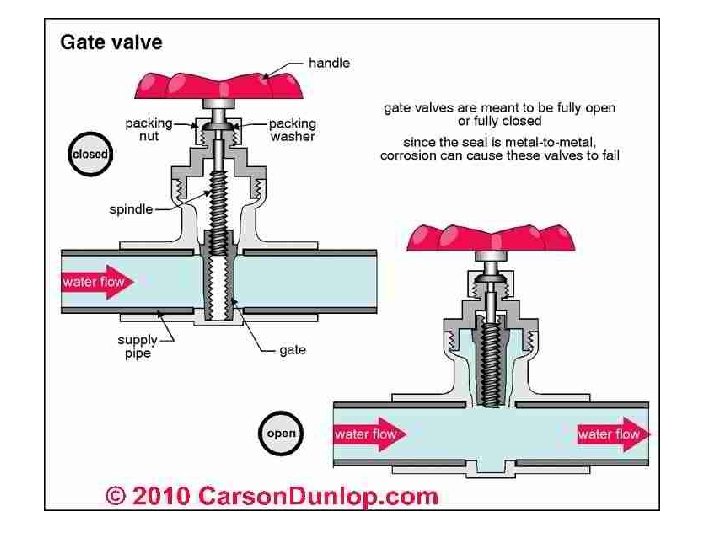
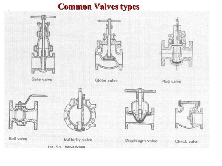
Appurtenances: To isolate and drain pipe section for test , installation , cleaning and repairs , a number of appurtenances are used. Sluice valve : - (Gate Valve) 1) Used for isolating or scouring the line. 2) Seal well under high pressure. 3) Offer little resistance to flow when fully open.
")
Sluice valve : - (Gate Valve)
 used to regulate and stop the flow on large")
Butterfly valve : - 1) used to regulate and stop the flow on large sized main. 2) Cheaper than sluice valve for larger sizes and occupy less space. 3) Offer high resistance when fully open. 4) rotating circular plate or a pair of hinged semicircular plates, attached to a transverse spindle and mounted inside a pipe in order to regulate or prevent flow.

Air valve : - Ø To release the trapped air at peak points in the main. Relief Valve: -

Ball Valve: a one-way valve that is opened and closed by pressure on a ball which fits into a cup-shaped opening.

Globe Valve: A globe valve, different from ball valve, is a type of valve used for regulating flow in a pipeline, consisting of a movable disk-type element and a stationary ring seat in a generally spherical body.
 Plug valves are valves with cylindrical or conically tapered")
Plug valve : - 1) Plug valves are valves with cylindrical or conically tapered "plugs" which can be rotated inside the valve body to control flow through the valve. 2) The plugs in plug valves have one or more hollow passageways going sideways through the plug, so that fluid can flow through the plug when the valve is open.
 In pressure & gravity conduits are provided at low")
Scour valve : - 1) In pressure & gravity conduits are provided at low points to drain off the line. 2) Their function is to allow periodic flushing of the lines to remove sediment and to allow the line to be drained for maintenance and repair work.
 A fire hydrant, also called fireplug, is a connection")
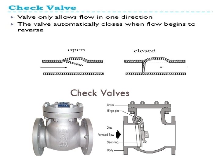
Fire Hydrant : - 1) A fire hydrant, also called fireplug, is a connection point by which firefighters can tap into a water supply. It is a component of active fire protection.
- Slides: 95